Renewable Transient Stability Modeling for Wind and Solar plants
This article covers how to model a wind or solar plant using the second generation wind turbine models that have been developed through WECC’s Model Validation Working Group (MVWG). The details of these models are explained in detail in PDF documents on the WECC website at the following link: WECC MVWG Approved Model Specifications
You can also download them directly from our website at:
- WECC Second Generation Wind Turbine Models 012314 (Summary of all wind turbine changes)
- WECC Type 1 and 2 Generic Turbine Pseudo Governor model – 1012 (Details on Type 1 and 2)
- WECC Type 3 Wind Turbine Generator Model – Phase II 012314 (Details on Type 3)
- WECC Type 4 Wind Turbine Generator Model – Phase II 012313 (Details on Type 4)
- WECC Solar PV Dynamic Model Specification – September 2012 (Details on PV model REEC_A.
In PowerWorld Simulator you use the following combination of models to model the various types of renewable generator models. Below we will provide examples of modeling the second generation Type 3 and 4 models and the Solar PV models.
| Type | Type 1 | Type 2 | 1st Gen Type 3 | 2nd Gen Type 3 |
1st Gen Type 4 | 2nd Gen Type 4 |
Solar PV |
| Machine | wt1g,WT1G1 | wt2g,WT2G1 | wt3g | regc_a | wt4g | regc_a | regc_a |
| Exciter | wt2e,WT2E1 | wt3e | reec_a | wt4e | reec_a | reec_b | |
| Governor | wt1t,WT12T1 | wt2t,WT12T1 | wt3t | wtgt_a | wt4t | wtgt_a | |
| Stabilizer | wt1p,WT12A1 | wt2p,WT12A1 | wt3p | wtgpt_a | |||
| Other\Aerodynamics | wtgar_a | ||||||
| Other\PRef Controller | wtgtrq_a | ||||||
| Other\Plant Controller | repc_a | repc_a | repc_a |
Demonstration of Wind and Solar models in PowerWorld Simulator
To demonstrate how the models fit together in PowerWorld Simulator we will use a small 6 bus system as an example. (Thanks to Pouyan Pourbeik from EPRI for making the original example cases and Ryan Elliot from Sandia National Labs for making these specific stability model examples). The original EPC and DYD files which Ryan Elliot from Sandia provided can be download from the following zip file (Example EPC and DYD files for renewable). These EPC and DYD files were read directly into PowerWorld Simulator (help on loading DYD files, help on loading EPC files).
Click on this paragraph to download a zip file that contains files for simulating either a PV plant, Type 3 Wind plant, or a Type 4 Wind plant. Then copy the contents of the zip file into a separate directory on your computer. This zip file contains the following files:
- RenewableDemo.pwb: PowerWorld Binary file with the small 6 bus case below
- RenewableDemo.pwd: PowerWorld Oneline display file
- PV Plant.aux: an Auxiliary file containing the stability models needed to model a PV Plant
- Wind Type 3.aux: an Auxiliary file containing the stability models needed to model a Type 3 Wind Plant
- Wind Type 4.aux: an Auxiliary file containing the stability models needed to model a Type 4 PV Plant
- ContingenciesAndPlots.aux: an Auxiliary file containing a transient contingency event, plot definitions, and result storage definitions
The case we’re using in this example is as shown in the following figure:
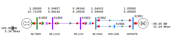
In this example, the generator on the left represents the renewable energy generator (bus 41905), while the generator on the right is modeled as an infinite bus (bus 41901) operating at a constant 1.05 per unit voltage and 60 Hz.
To model a Type 3 wind turbine you must enter models as described in the table above for all of the different generator model types. You can do this in many ways:
- Load them from a DYD file (help on loading DYD files)
- Enter them in manually using the generator dialog (help topic on transient stability data object dialogs)
- Edit the value in the Model Explorer (help topic on editing transient stability data)
- Choose File\Load Auxiliary File to load them from an Auxiliary File such as the three contained in the zip file (Wind Type 3.aux, Wind Type 4.aux, and PV Plant.aux)
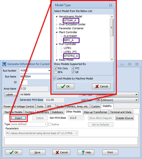
As an example, the following image shows what happens when you click Insert for Other Models on the Generator dialog’s Stability tab.
To demonstrate what to do once you have the models, we’ll just use the Auxiliary Files for this example. After you have copied the contents of the zip file into its own directory, do the following to go through this transient stability demonstration:
- Choose File>Open Case and then choose the file RenewableDemo.pwb. This will also open the oneline diagram file RenewableDemo.pwd.
- Choose File>Load Auxiliary File and then choose the file ContingenciesAndPlots.aux
- In Run Mode, got to the Add Ons Ribbon Tab and choose Transient Stability… button to open the Transient Stability Dialog.
- At the bottom of that dialog choose Load All Settings From>Load Auxiliary…
- Choose the file Wind Type 3.aux and click Open.
- Choose Yes on the dialog that appears to clear out any existing transient stability models in the case. You would not always do this, but in this example it is convenient to do so.
- Click the Run Transient Stability button in the upper left of the dialog
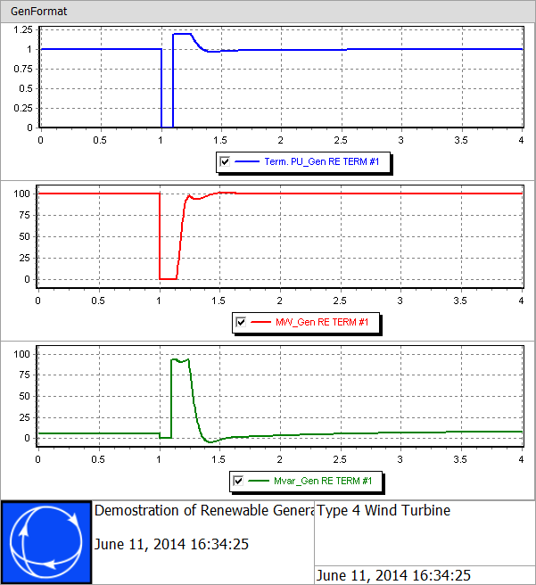
- The case is configured to apply a fault at 1.0 seconds at Bus 41902 and then at 1.1 seconds clear this fault and open the branch from bus 41901 – 41906. It is also configured to store certain information and then automatically display plots showing the results. This article concentrates only on defining the stability models themselves and running the simulation. See the online help for more information on defining transient contingencies, results to save, and plot definitions in transient stability.
- Do the same but open the file Wind Type 4.aux or PV Plant.aux to simulate those devices. In this particular example the PV Plant and Wind Type 4 models are configured so that they actually give an identical response, but you can tweak the parameters from these examples to see how things change.
The following shows the plot results for Type 3 Wind Turbine.

The following shows the plot results for Type 4 Wind Turbine.
Tags: Presentation,Product,Simulator,Transient Stability,Tutorial,Type
June 11, 2014