Renewable Generators: Voltage Droop Control with Deadband in Power Flow Solution
This article discusses a new feature that will be available in PowerWorld Simulator 21 when it released in 2019. If you are a customer of PowerWorld Simulator who is interested in testing the feature before Simulator 21 is released, please contact PowerWorld Corporation at info@powerworld.com.
- Presentation on Voltage Droop Control with Deadband
- White Paper on Voltage Droop Control with Deadband
- Example Case PDF
- Example Case ZIP file with case files
Typical Renewable Energy Plant Network Model

It is common for wind and solar plants to be modeled as a generator (bus 2 above) connected to an equivalent step-up transformer (bus 2 – 3), in series with an equivalent feeder (bus 3 – 4) and then a substation transformer (bus 4 – 1). One could imagine the generators connected at 0.5 kV, a 10 kV feeder, and then a 10 to 115 kV transformer at the point of interconnection. In this configuration, the plants are often not configured with a traditional “voltage setpoint”, but instead follow a voltage droop control with control centered at the point of interconnection. The voltage droop control is then specified by the user to follow a QV characteristic curve which is a function of the RegBus voltage and the purpose of the curve is to enforce that the total reactive flow going into the RegBus from the respective VoltageDroopControl is equal to this value. The curve will have the following shape.
Voltage Droop with Dead-Band Characteristic

To model this in a set of power flow equations, we must introduce a new type of equation. The equations at bus 1, 3, and 4 would remain the same with typical Q equations that take the summation of reactive flows going into the bus and sum them to zero. The equation at bus 2 however is replaced by a new equation that specifies that the flow on the branch arriving bus 1 from bus 4 is equal to the QV-characteristic function.
A presentation has been made to cover the background of applying Voltage Droop Control with Deadband to the power flow solution. In addition, a very detailed white paper has been written providing more theoretical background thorough treatment of how to implement this so it does not cause numerical problems in the power flow solution.
- Presentation on Voltage Droop Control with Deadband
- White Paper on Voltage Droop Control with Deadband
The presentation and white paper discuss the wrinkles associated with this new concept that complicate the numerical implementation of these equations in the power flow including the following.
- The function is continuous, but the derivative of this function is discontinuous. Discontinuous derivatives introduce numerical difficulties that are addressed by smoothing this function at the corners. This is described in great detail in the white paper.
- Multiple generator buses can act together to perform this VoltageDroopControl. They coordinate their control in the same way that remote voltage regulation sharing is done for voltage control.
- Multiple VoltageDroopControl functions can be applied to the same regulated bus with different sets of generators belonging to each VoltageDroopControl equation
- Care must be taken when multiple regulated buses areconnected by very low impedance branches. This can create numerical troubles in the solution which must be taken into account.
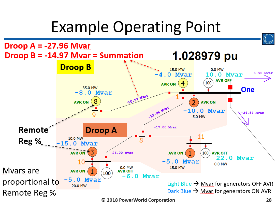
Example Results are shown in the two images below with 2 separate VoltageDroopControl regulating bus One.

The presentations above were made at two meetings in November 2018.
- NERC SAMS meeting on November 7, 2018 at MISO offices in Eagan, Minnesota.
- WECC MVWG meeting on November 29, 2018 at WECC offices in Salt Lake City, Utah.
Tags: Presentation,Simulator,Technical Papers
October 24, 2018