Case Study in Using Auxiliary File Scripting with Advanced Filters, Custom Floats, and Expressions
This is a case study that demonstrates how to automate the process of replicating the net reactive capability curve from a set of renewable generators behind a small distribution system which is connected to a single utility bus. This serves as a wonderful example for demonstrating several topics.
- Use of auxiliary files to automate processes
- Advanced filtering
- Custom floating point values
- Expressions
All of the cases, onelines, auxiliary files, and result files in the following example can be downloaded from the following zip file link: KnowCaseStudyScripting_Filter_Custom_Expression.zip
| File | Description |
| PV_Field_8Bus.pwb | A Simulator example case |
| PV_Field_8Bus.pwd | A Simulator oneline diagram |
| CaseSetup.aux | Defines some Filters, Custom Floats, and Expressions. |
| SolutionEnforceCurrentQMax.aux | Auxiliary File with a SCRIPT section for enforcing PV generators at current limits |
| SolutionEnforceCurrentQMin.aux | Auxiliary File with a SCRIPT section for enforcing PV generators at current limits |
| TraceCurve.aux | Traces the capability curve |
| ScriptExample.aux | Overall Script that uses all the stuff above |
| UtilityPoints.csv | The raw results CSV that the script generates |
| UtilityPoints.xlsx | The Excel file manually edited to generate your plot. |
As an example consider the power system below which has the following characteristics.
- Three solar generators at the bottom representing our renewable generators
- Various transmission lines and transformers represent the connection point to the rest of the system
- Generator at the top bus named “Utility” representing the interconnection point to the rest of the system.
The case and oneline below are contained files PV_Field_8Bus.pwb and PV_Field_8Bus.pwd.
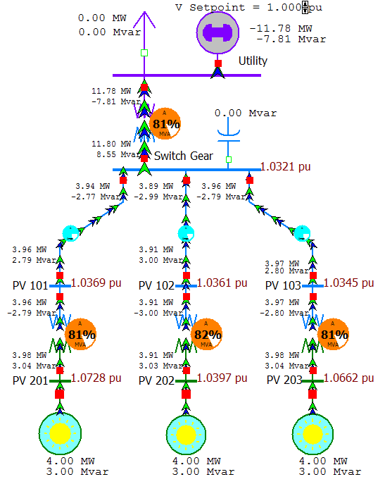
The generator at the top is modeled as the slack bus, and our user is interested in what the net injection the utility will see as the solar generators operating on the edge of their own capability curves. The goal of this case study will be to ramp the three solar generators to various MW outputs and then at each MW output set the solar generators to their maximum Mvar values and determine for each MW/Mvarmax value what the resulting flows will be seen at the utility generator.
Advanced Filtering
For more detailed help on Advanced Filtering see the online web help at the following link: Advanced Filtering Help Topic.
It will be convenient in this example to set particular values for all PV generators via one script command. More complicated examples may include dozens or move PV generators so we may want to set the MW output of all them to the same value via on script command. This is greatly aided by defining advanced filters. For this particular example we will create an advanced filter for generators that tests the Name of the Bus to which the generator is connected. All PV generators in the case are connected to a bus whose name starts with the string “PV”. Another filter will be created for generators connected to a bus who name starts with “Utility”.

Custom Floating Point Values
For more detailed help on Custom Fields and Custom Field Descriptions, see the online web help at the following link: Custom Field Help Topic.
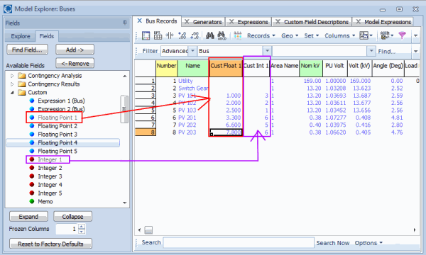
Every data record in PowerWorld Simulator has associated with it a set of custom floating point, custom integer, and custom string values. These values are not used directly by any calculations in PowerWorld Simulator but are there for convenience when a user needs to specify input data (or output data) that is not presently defined in the software. This example presents two examples of this. The Mvar output of the generators are going to vary according to two custom input values we’ll call INomMax and Qmaxabs.
INomMax will be defined as the current limit of the generator expressed in nominal MVA. For the example below we use a maximum current rating of 5.0 nominal MVA. By this we mean the maximum MVA is 5.0 MVA at 1.0 per unit voltage and then varies linearly with the per unit voltage at the terminal bus varies. Thus at 1.05 per unit voltage the actual MVA limit is 5.25 MVA and at 0.95 per unit voltage the actual MVA limit is 4.75 MVA.
Qmaxabs represents an additional constraint on the maximum Mvar output of the generator.
A user of PowerWorld Simulator can simply add these columns to a case information display and then enter values under these custom values as shown in the following figure.
To help with the user interface interaction for these custom defined fields, a user can also defined field names and column headers for these. This is done by going to the Model Explorer and navigating to Case Information and Auxiliary\Custom Field Descriptions as shown in the following figure. The following figure shows that the GEN object type has defined captions for fields and headers for the first two generator custom floats.
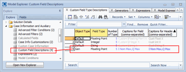
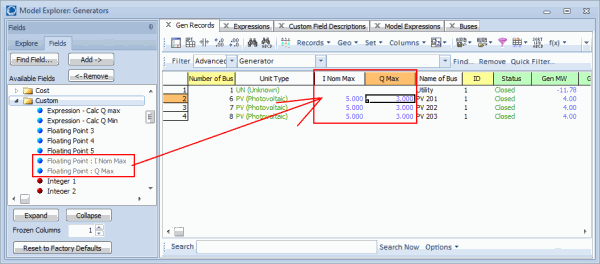
By defining these custom field descriptions, the user interface in simulator will look nicer such as shown in the following figure.
Expressions
For more detailed help on Expressions, see the online web help at the following link: Expressions Help Topic
In our example we will be assuming a fixed MW output (Pout) at a particular solution, so therefore given the current limit expressed in nominal MVA (INomMax) then the MVar output will vary with the per unit terminal voltage (Vpu) according to the following equation
( (INomMax*Vpu)2 – Pout2 )0.5
We then also enforce that the Mvar output can go no higher than another user input Qmaxabs. For a generator for which INomMax = 5.0 and Qmaxabs = 3.0, then the following figure shows what the Mvar value will be as a function of MW for three different values of per unit voltage.
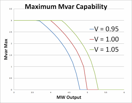
These functions can be described by define an Expression in PowerWorld Simulator. The expression will end up being a function for 4 values
- Generator MW Output
- Per unit voltage magnitude of the generator bus
- INomMax which will be populated in a Custom Floating Point number
- Qmaxabs which will be populated in a Custom Floating Point number
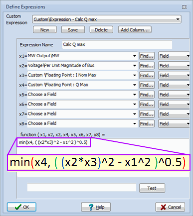
The resulting expression is defined in Simulator on the following dialog.
Trick to enforce generator current rating using “@CustomExpression:0”
To actually solve the power flow while enforcing the current limit the following pieces of Simulator AUX file script are written. Note that the use of the value “@CustomExpression:0” inside the SetData() command tells Simulator to set the GenMVR value equal to the present value of the field CustomExpression:0. This allows us to use our custom expression to set the GenMVR output directly.
SCRIPT
{
// Set all PV generators to 3.5 MW
// (makes use of our advanced filter)
SetData(Gen, [GenMW], [3.5], "PV Gens");
// Set all PV generators equal to the custom expression
SetData(Gen, [GenMVR], ["@CustomExpression:0"], "PV Gens");
// Solve the Power Flow
SolvePowerFlow;
}
|
This won’t work exactly though, because when we solve the power flow, the voltage at the terminal bus of the generator is going to change and thus the custom expression might change and we should change our generator Mvar output. To do this via only an AUX file, we’ll just repeatedly call two commands 10 times instead assuming they will eventually converge to a solution. (This could be done more elegantly using SimAuto, but that’s a knowledge base post for another day).
SetData(Gen, [GenMVR], ["@CustomExpression:0"], "PV Gens"); SolvePowerFlow; SetData(Gen, [GenMVR], ["@CustomExpression:0"], "PV Gens"); SolvePowerFlow; SetData(Gen, [GenMVR], ["@CustomExpression:0"], "PV Gens"); SolvePowerFlow; Etc... |
Other Script Commands Used
For more detailed help on the Auxiliary File and the SCRIPT commands, see the website help for Auxiliary Files.
The voltage at the utility bus is set by using the SetData script command as follows (with 0.95 replaced as is appropriate).
SetData(Gen, [BusNum, GenID, GenVoltSet], [1, "1", 0.95]);
Inside our script to write out all the data for use in the compilation of results, we use the script command SaveDataWithExtra as follows.
SaveDataWithExtra("UtilityPoints.csv", CSVNOHEADER, Gen, [GenMW, GenMVR], [], "Utility", [], ["P"], ["0.0"]);
Notice again that we are using another Advanced Filter named “Utility” that allows us to automatically write out the MW and Mvar values at the utility generator. In addition we write out some extra information about which particular datapoint this represents.
Putting it all together in a SCRIPT
For more detailed help on the Auxiliary File and the SCRIPT commands, see the website help for Auxiliary Files.
The entire process is now automated by opening the case we started with “PV_Field_8Bus.pwb” and then loading the Auxiliary File ScriptExample.aux. There are 5 total scripts that are called with the following relationships.
- ScriptExample.aux (Master Script)
- CaseSetup.aux (Sets up Filters, Custom Floats, Expressions)
- TraceCurve.aux (Traces the curve at a particular Utility Voltage)
- SolutionEnforceCurrentQMax.aux (Tricks the enforcement of Qmax)
- SolutionEnforceCurrentQMin.aux (Tricks to enforcement of Qmin)
Again, all these files can be downloaded in a zip file at the following link: KnowCaseStudyScripting_Filter_Custom_Expression.zip
At the end of this post we also list all the script files.
Results Generated
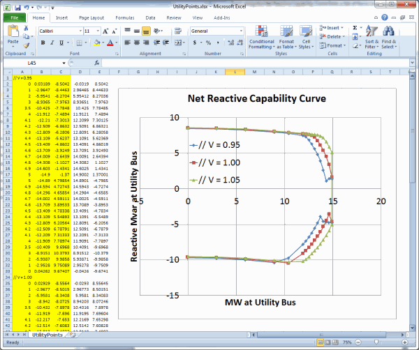
The results of this script are a CSV file which can then be used to import into a spreadsheet program to create graphs of the resulting Net Capability Curve. These result file is in the zip file (KnowCaseStudyScripting_Filter_Custom_Expression.zip) as well as an Excel Spreadsheet showning the resulting capability curve. This is depicted in the following image.
Script Files
Below are summaries of the SCRIPT files themselves to view
ScriptExample.aux
SCRIPT
{
LoadAUX("CaseSetup.aux");
// Make small convergence tolerance because dealing with small values
// Typical MVA base for the system is 100 MVA, following in "per unit"
// Thus the tolerance is 0.001 MVA (1 kva)
SetData(Sim_Solution_Options, [ConvergenceTol], [0.00001], All);

// Configure all generators to be have no AVR, we'll just manual set them
SetData(Gen, [GenAVRAble, GenUseCapCurve], ["NO", "NO"], All);

// Change all the "I Nom Max" values to 5.0 and "Qmax" values to 3.0
SetData(Gen, [CustomSingle:0, CustomSingle:1], [5.0, 3.0], "PV Gens");

// clear out the existing results file
DeleteFile("UtilityPoints.csv");

WriteTextToFile("UtilityPoints.csv", "// V = 0.95");
SetData(Gen, [BusNum, GenID, GenVoltSet], [1, "1", 0.95]);
LoadAUX("TraceCurve.aux");
WriteTextToFile("UtilityPoints.csv", "// V = 1.00");
SetData(Gen, [BusNum, GenID, GenVoltSet], [1, "1", 1.00]);
LoadAUX("TraceCurve.aux");

WriteTextToFile("UtilityPoints.csv", "// V = 1.05");
SetData(Gen, [BusNum, GenID, GenVoltSet], [1, "1", 1.05]);
LoadAUX("TraceCurve.aux");
}
CaseSetup.aux
//--------------------------------------------------------------------------
// Generator Filters to make Scripts cleaner and more general
//--------------------------------------------------------------------------

DATA (FILTER, [ObjectType,FilterName,FilterLogic,FilterPre,Enabled],
               AUXDEF, YES)
{
"Gen" "PV Gens" "AND" "NO " "YES"
 <SUBDATA Condition>
 BusName startswith "PV"
 </SUBDATA>
"Gen" "Utility" "AND" "NO " "YES"
 <SUBDATA Condition>
 BusName startswith "Utility"
 </SUBDATA>
}
//--------------------------------------------------------------------------
// Simulator has "custom floats" with each object that Simulator does not
// use directly. These can be used to store extra user needed data
// This "CUSTOMFIELDDESCRIPTION" object allows you to provide "names" for
// these fields to make the user interface easier to understand
// Below we define for a generator object the following
// "CustomSingle:0" is the "I Nom Max" value
// "CustomSingle:1" is the "Q Max" value
// The "I Nom Max" is a value expressed in MVA for the maximum current
// at 1.0 per unit (nominal) voltage
// Thus if "I Nom Max" = 5.0 MVA, then
// at 0.95 per unit the max is 4.75 MVA
// at 1.00 per unit the max is 5.0 MVA
// at 1.05 per unit the max is 5.25 MVA
// By "Q max" we mean an absolute limit on Q expressed in Mvar
//--------------------------------------------------------------------------
DATA (CUSTOMFIELDDESCRIPTION, [ObjectType,CustomType,CustomMaxOfType,
CustomFieldCaption,CustomHeaderCaption], AUXDEF, YES)
{
"Gen" "Floating Point" 5 "I Nom Max,Q Max" "I Nom Max,Q Max"
}
//--------------------------------------------------------------------------
// Simulator also allows you to create a custom expression which is a
// function of other fields for an object
// Below I create one called "Calc Q max" which is equal to the MINIMUM of
// ( (INomMax*Vpu)^2 - MW^2 ) ^0.5
// ( Qmax )
// This will mimic the Maximum Mvar capability curve exactly
// Then create a second custom expression that is  the negative of the first
//--------------------------------------------------------------------------
DATA (CUSTOMEXPRESSION, [ObjectType,ObjectType:1,CustomExpressionString,
VariableName,VariableName:1,VariableName:2,VariableName:3], AUXDEF, YES)
{
"Gen:1" "Calc Q max" "min(x4, ( (x2*x3)^2 - x1^2 )^0.5)" "GenMW" "BusPUVolt"
                    "CustomSingle" "CustomSingle:1"
"Gen:2" "Calc Q Min" "- x1" "CustomExpression" "" "" ""
}
TraceCurve.aux
SCRIPT
{
// P = 0.0
SetData(Gen, [GenMW], [0.0], "PV Gens");
LoadAux("SolutionEnforceCurrentQMax.aux");
SaveDataWithExtra("UtilityPoints.csv", CSVNOHEADER, Gen, [GenMW, GenMVR],
                  [], "Utility", [], ["P"], ["0.0"]);
// P = 1.0
SetData(Gen, [GenMW], [1.0], "PV Gens");
LoadAux("SolutionEnforceCurrentQMax.aux");
SaveDataWithExtra("UtilityPoints.csv", CSVNOHEADER, Gen, [GenMW, GenMVR],
                  [], "Utility", [], ["P"], ["1.0"]);
Repeat for numerous values of P = 2,3,3.5,4,4.1,4.2,4.3,4.4,4.5,4.6,4.7,4.8

// P = 4.9
SetData(Gen, [GenMW], [4.9], "PV Gens");
LoadAux("SolutionEnforceCurrentQMax.aux");
SaveDataWithExtra("UtilityPoints.csv", CSVNOHEADER, Gen, [GenMW, GenMVR],
                  [], "Utility", [], ["P"], ["4.9"]);
// P = 5.0
SetData(Gen, [GenMW], [5.0], "PV Gens");
LoadAux("SolutionEnforceCurrentQMax.aux");
SaveDataWithExtra("UtilityPoints.csv", CSVNOHEADER, Gen, [GenMW, GenMVR],
                  [], "Utility", [], ["P"], ["5.0"]);
// P = 5.0
SetData(Gen, [GenMW], [5.0], "PV Gens");
LoadAux("SolutionEnforceCurrentQMin.aux");
SaveDataWithExtra("UtilityPoints.csv", CSVNOHEADER, Gen, [GenMW, GenMVR],
                  [], "Utility", [], ["P"], ["5.0"]);
// P = 4.9
SetData(Gen, [GenMW], [4.9], "PV Gens");
LoadAux("SolutionEnforceCurrentQMin.aux");
SaveDataWithExtra("UtilityPoints.csv", CSVNOHEADER, Gen, [GenMW, GenMVR],
                  [], "Utility", [], ["P"], ["4.9"]);
Repeat for numerous values of P = 4.8,4.7,4.6,4.5,4.4,4.3,4.2,4.1,4,3.5,3,2

// P = 1.0
SetData(Gen, [GenMW], [1.0], "PV Gens");
LoadAux("SolutionEnforceCurrentQMin.aux");
SaveDataWithExtra("UtilityPoints.csv", CSVNOHEADER, Gen, [GenMW, GenMVR],
                  [], "Utility", [], ["P"], ["1.0"]);
// P = 0.0
SetData(Gen, [GenMW], [0.0], "PV Gens");
LoadAux("SolutionEnforceCurrentQMin.aux");
SaveDataWithExtra("UtilityPoints.csv", CSVNOHEADER, Gen, [GenMW, GenMVR],
                  [], "Utility", [], ["P"], ["0.0"]);
}
SolutionEnforceCurrentQMax.aux
Note that the use of the value “@CustomExpression:0” inside the SetData() command tells Simulator to set the GenMVR value equal to the present value of the field CustomExpression:0. This allows us to use our custom expression to set the GenMVR output directly to whatever the present maximum Mvar expression evaluates to.
SCRIPT
{
// Set Mvar output based on expression and resolve
// Just automatically do this 10 times.
SetData(Gen, [GenMVR], ["@CustomExpression:0"], "PV Gens"); SolvePowerFlow;
SetData(Gen, [GenMVR], ["@CustomExpression:0"], "PV Gens"); SolvePowerFlow;
SetData(Gen, [GenMVR], ["@CustomExpression:0"], "PV Gens"); SolvePowerFlow;
SetData(Gen, [GenMVR], ["@CustomExpression:0"], "PV Gens"); SolvePowerFlow;
SetData(Gen, [GenMVR], ["@CustomExpression:0"], "PV Gens"); SolvePowerFlow;
SetData(Gen, [GenMVR], ["@CustomExpression:0"], "PV Gens"); SolvePowerFlow;
SetData(Gen, [GenMVR], ["@CustomExpression:0"], "PV Gens"); SolvePowerFlow;
SetData(Gen, [GenMVR], ["@CustomExpression:0"], "PV Gens"); SolvePowerFlow;
SetData(Gen, [GenMVR], ["@CustomExpression:0"], "PV Gens"); SolvePowerFlow;
SetData(Gen, [GenMVR], ["@CustomExpression:0"], "PV Gens"); SolvePowerFlow;
}
SolutionEnforceCurrentQMin.aux
Note that the use of the value “@CustomExpression:1” inside the SetData() command tells Simulator to set the GenMVR value equal to the present value of the field CustomExpression:1. This allows us to use our custom expression to set the GenMVR output directly to whatever the present minimum Mvar expression evaluates to.
SCRIPT
{
// Set Mvar output based on expression and resolve
// Just automatically do this 10 times.
SetData(Gen, [GenMVR], ["@CustomExpression:1"], "PV Gens"); SolvePowerFlow;
SetData(Gen, [GenMVR], ["@CustomExpression:1"], "PV Gens"); SolvePowerFlow;
SetData(Gen, [GenMVR], ["@CustomExpression:1"], "PV Gens"); SolvePowerFlow;
SetData(Gen, [GenMVR], ["@CustomExpression:1"], "PV Gens"); SolvePowerFlow;
SetData(Gen, [GenMVR], ["@CustomExpression:1"], "PV Gens"); SolvePowerFlow;
SetData(Gen, [GenMVR], ["@CustomExpression:1"], "PV Gens"); SolvePowerFlow;
SetData(Gen, [GenMVR], ["@CustomExpression:1"], "PV Gens"); SolvePowerFlow;
SetData(Gen, [GenMVR], ["@CustomExpression:1"], "PV Gens"); SolvePowerFlow;
SetData(Gen, [GenMVR], ["@CustomExpression:1"], "PV Gens"); SolvePowerFlow;
SetData(Gen, [GenMVR], ["@CustomExpression:1"], "PV Gens"); SolvePowerFlow;
}
Tags: How-to,Script,Simulator,Tip,Tutorial
June 6, 2013