Motor Load Starting using Transient Stability
Note: Download a small sample case at the following link which is used in this demonstrate: MotorStart Case
Note: Starting in the July 10, 2013 patch of Simulator 17, a modification was made to automatically change the integration time step for the entire simulation when induction motors (loads) or induction machine (generators) drop below 0.1 per unit speed. A multiplier is hard-coded internal to Simulator that is 0.05 at 0.0 per unit speed and increases linearly up to 1.0 at 0.1 per unit speed. The time step used by the integration will be equal to the user-specified time step multiplied by this value. If multiple motors/machines are operating in this region, then the smallest multiplier in the case will be used. This is intended to improve induction motor starting studies without the user having to manually reduce the time step for the entire simulation. It will be a very rare event when this occurs, largely only occurring during motor start studies. This new feature will make the plots shown in the following figures different than what you would get with Simulator 17 in a patch after July 10. However, the example remains educational.
In Transient Stability, when a dynamic model is not online in the initial condition, without using a special model that dynamic model can not be closed in during the transient stability simulation. For example, PowerWorld Simulator does not permit a synchronous machine to be closed during the simulation and thus modeling the start-up of a synchronous generator is not presently possible (as of June 2013). In general the same is true for dynamic load models such as the MOTORW, CIMW, or CMPLDW motor models. These models can not be closed during a stability simulation.
To model motor starting however, there are special models which have been designed to model starting. There are older models that are assigned to generators (with a negative MW output) such as MOTOR1 and CIMTR4, as well as models assigned to a load record such as CIM5 and CIM6. For this knowledge base article, we will discuss the CIM5 and CIM6 induction motor models.
This article will not go into detail about induction motor circuit parameters (Ra, Xa, Xm, R1, X1, R2, X2) and how these relate to values used in transient stability models of induction motors (Ra, Xs, Xp, Tpo, Xpp, Tppo). All the induction motors and machines treat these conversions the same. What is different about the CIM5 and CIM6 induction motors is how the load torque (the mechanical torque) on the motor is modeled.
For any induction motor, from initializing the circuit model of an induction motor PowerWorld Simulator will determine the initial slip and the initial load torque (Tloadinit). The initial per unit speed is then just 1 – slip. Given the initial speed (ω0) and the initial load torque (Tloadinit), the initialization of a motor that is closed and operating in the steady state initial condition is as follows.
| Model Name | Parameters | Load Torque Equation | Online Initialization |
| CIM5 | Tnom, D | Tload = TnomωD | Tnom=Tloadinit/(ω0D) |
| CIM6 | Tnom, A, B, C0, D, E |
Tload = Tnom(Aω2+Bω + C0 + DωE) | C0= 1 – Aω02-Bω0 – Dω0E Tnom=Tloadinit |
Any values specified by the user for (C0 and Tnom) in the model input parameters will be ignored if the load is online in the initial condition. However, when you want to perform a motor starting simulation, then these parameters (C0 and Tnom) much be specified as part of the model input parameters and will help determine the ultimate response of the load. Another very important consideration when studying motor starting is deciding what integration time step to use. Induction motors operating at low speeds have extremely fast electrical transients, and since motor starting involves going from zero speed, motor starting involves extremely fast transients. Because of this, for a motor starting study you may need to use a much smaller time-step than use in other types of stability studies. (Note: Simulator does make use of multirate timestep integration to better handle these fast motor transients, but you will still need to reduce the time step some.)
To demonstrate this a small sample case has been made and can be found at the following link: MotorStart Case
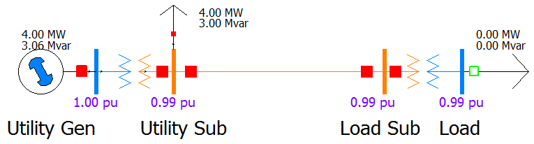
The case has a small generator and load (4 MW) at the Utility Gen and Utility Sub buses and an initially open load at the Load bus.
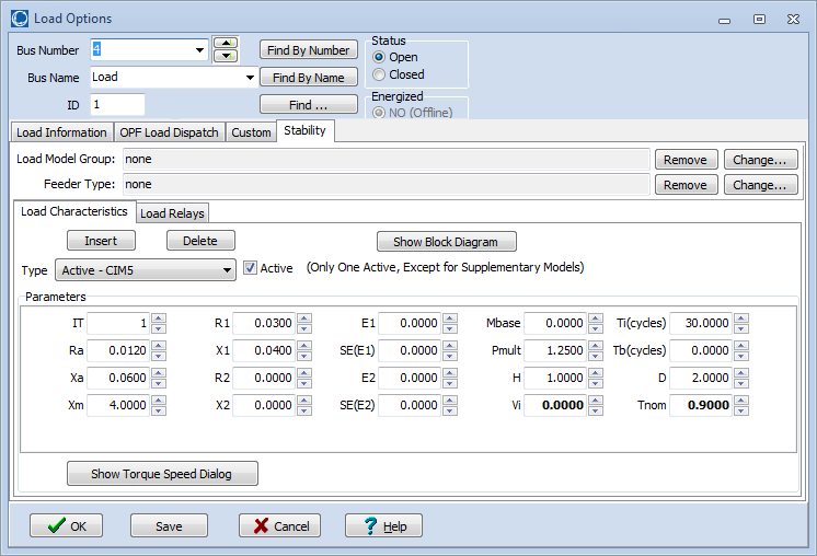
The load model at the Load bus is set to CIM5 as shown in the following figure. A value of Tnom is specified as 0.9 per unit. Note also that the value of Vi is set to 0. The CIM5, like many induction motor models, includes an under-voltage tripping feature such that if the terminal voltage falls below Vi for more than Ti cycles, then the load will trip. We don’t want that to happen in this example, so Vi is set to 0.
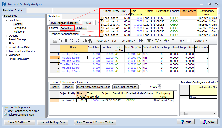
We then configure the transient stability tool to CLOSE in this load at 1.0 seconds of simulation. To demonstrate the impact of choosing a time step, below we have create 6 different transient contingencies which all have different time steps varying from 0.5 ms up to 8.0 ms. Each contingency though has the same single event – Load ‘4’ ‘1’ CLOSE.
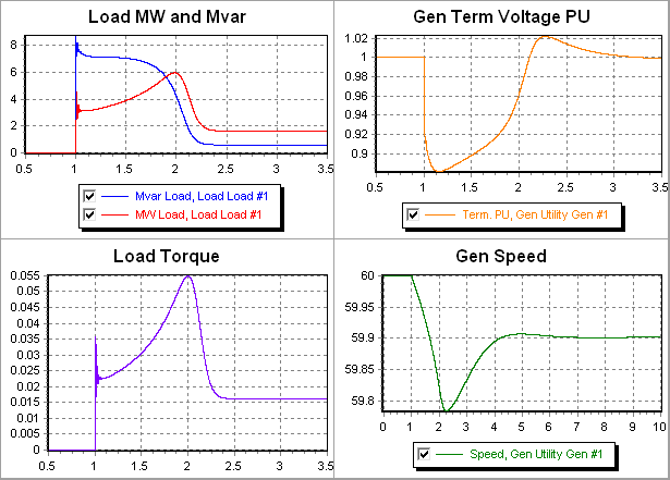
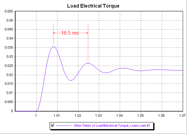
The following plot shows several response curves when using the 0.5 ms time-step. You can see squiggles at 1.0 seconds which represent those very fast electrical transients mentioned earlier.
The following figure shows a close-up of the Load Torque curves between 0.99 and 1.07 seconds. The period of this initial oscillation is 16.5 ms and thus is about a 60 Hz oscillation. As a result our normal integration methods which use between 4 and 8 ms time steps may present some trouble.
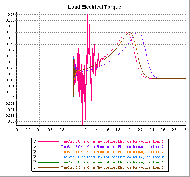
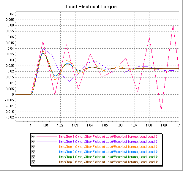
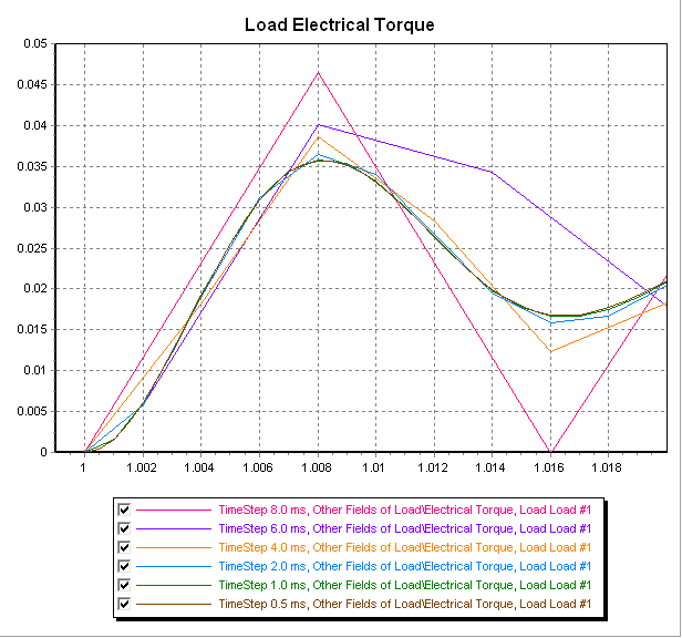
To demonstrate this we ran the same simulation using 6 different time steps between 0.5 ms and 8.0 ms. The load’s electrical torque for each of these different time-steps is shown in the following figure. You can see that using any time step between 0.5 and 4.0 ms works acceptably, but the 6 ms and 8 ms time-steps show some numerical instability. The images after that also show that as you make the time step smaller you’re able to more precisely go through these fast oscillation, but when looking at the overall system behavior the 4 ms time-step still yields a response substantially similar to the 0.5 ms time step.
Tags: How-to,Simulator,Transient Stability,Tutorial
July 2, 2013