Creating Diagrams: Auto-Insert Buses/Substations
PowerWorld can store geographic latitude/longitude coordinates for bus and substation objects. You can automatically insert these objects into your system diagrams using either the specified geographic coordinates, or x/y coordinates imported from a file.
Note: Auto-insert buses is only for inserting bus objects on the diagram representing existing data. In other words, you cannot use the auto-insert buses routine to add new buses to the system model. See topics on loading data from auxiliary files or from spreadsheet applications for information on creating new buses (or other objects) in an existing load flow case.
Select Insert >> Auto-Insert >> Buses (or Substations) from the main menu.
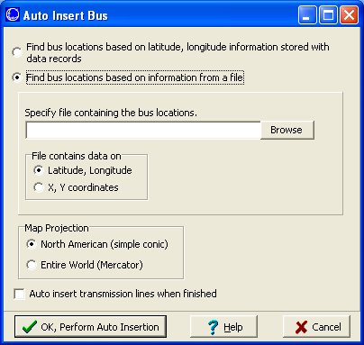
Auto Insert Buses Dialog
Insert by latitude, longitude
If you have stored latitude and longitude information with the Bus records in Simulator, you can use that information to automatically insert the buses on a oneline diagram. Select the option on the dialog for finding bus locations based on latitude, longitude information stored with the data records. When selected, the Map Projection option will become enabled. Choose what type of projection you would like to be used for placing the buses on the diagram.
If you would like Simulator to automatically insert transmission lines after completing the auto insertion of your buses, check the applicable box at the bottom of the Auto-Insert dialog. Transmission lines and transformers will be automatically drawn based on the Line/XFMR options defined in Default Drawing Values.
Click OK to insert the buses on your diagram. Click Cancel to exit the process without inserting the buses.
Insert by locations specified in a file
You must first specify the file containing the location data. You must also specify whether the file contains x,y coordinates, or longitude, latitude coordinates. The format of the location data text file is as follows:
- The first line of the file is ignored by Simulator.
- The remaining lines are comma-delimited and each contain three values:
Bus Number, X value, and Y value. - For geographic coordinates, X represents longitude and Y represents latitude.
Num, X, Y
1, 24001.46, 19715.15
3, 24001.46, 19715.15
16, 24130.91, 19638.99
17, 24007.31, 19093.09
21, 23649.27, 18439.07
22, 23649.27, 18439.07
etc…
Simulator will place the buses on the oneline diagram at specified coordinates. If the file contains geographic coordinates, select the Map Projection you would like to be used when converting the latitude, longitude values from the file; this should be the same projection used when inserting borders into your diagram. The buses will be drawn according to the bus options specified in Default Drawing Values.
If you would like Simulator to automatically insert transmission lines after completing the auto insertion of your buses, check the applicable box at the bottom of the Auto-Insert dialog. Transmission lines and transformers will be automatically drawn based on the Line/XFMR options specified in Default Drawing Values.
Click OK to insert the buses on your diagram. Click Cancel to exit the process without inserting the buses.
Next Tip: Auto-Insert Other Objects
Tags: How-to,Simulator,Tutorial
June 28, 2012

