Bus Display Objects
In power system analysis, the term "bus" is used to refer to the point where a number of electrical devices, such as lines, loads or generators, join together. On the oneline diagram, buses are usually represented with either a thick horizontal line or a thick vertical line. The bus thickness and color can be customized.
Right-clicking on the bus will display its local menu. The local menu offers you the chance to view the corresponding Bus Dialog, the Quick Power Flow List, and the Bus View Display. When the application is in Edit Mode, the local menu will also allow you to add bus fields to the bus and to insert any undrawn buses connected to the selected bus. Bus Fields are often placed close to the bus to indicate its voltage magnitude, voltage angle, and other relevant information. A more complete description of
Edit Mode
To add a new bus to the case graphically, follow this simple procedure:
- Select Network > Bus from the Individual Insert ribbon group of the Draw ribbon tab. This prepares Simulator to insert a new bus.
- Left-click on the oneline background at the location where you want to place the new bus. This invokes the Bus Option Dialog.
- Use the Bus Option Dialog to specify the number, name, size, thickness, orientation, area, zone, and nominal voltage of the bus, as well as the load and shunt compensation connected to it. Every bus must have a unique number.
- The Bus Option Dialog will include a message just above the Bus Number field indicating that a new bus will be inserted into the power system data model. This will appear as long as the Bus Number that is selected does not already exist in the power system case.
- Click OK on the Bus Option Dialog to finish creating the bus and to close the dialog. If you do not wish to add the bus to the case, click Cancel.
If you are simply adding a symbol to the oneline diagram for a bus that has already been defined in the case, many of the parameters you are asked to specify in step three will be filled in for you.
To modify the parameters for an existing bus, position the cursor on the bus and right-click to invoke the bus' local menu. From the local menu, choose Bus Information Dialog to view the associated Bus Dialog. You may change any of the parameters specified there. When a bus' number is changed, the bus numbers associated with all of the devices attached to that bus are also automatically changed. To renumber several buses simultaneously, please see Bus Renumbering Dialog.
To modify any aspect of a bus' appearance, first select the bus, and then click any of the format buttons found in the Formatting ribbon group on the Draw ribbon tab. You can change the length of the bus (but not its thickness) by dragging the bus' resizing handles.
In order to delete an existing bus after selecting it, use either the Cut button, found in the Clipboard ribbon group on the Draw ribbon tab, to preserve a copy of the bus on the Windows clipboard, or Delete button, found in the Clipboard ribbon group on the Draw ribbon tab, to remove the bus without copying it to the clipboard. You will be asked whether you want to remove both the display object and its associated bus record, or merely the display object, leaving the bus in the power flow model. If you will never be deleting a record from the power system model, you may also choose the option labeled Always Delete Objects Only. Be careful when deleting existing buses with attached devices. An error will occur during validation if you do not also delete the attached devices or attach them to other buses.
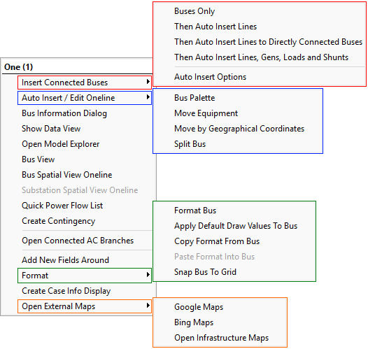
Local Menu for Bus Display Objects
When right-clicking of a single Bus Display object in Edit mode a very large drop-down menu appears as shown in the image below. The first entry in this menu can not be clicked on and will show the Name of the Bus and then the Number of the bus enclosed in parantheses. Under this there are several options
|
|