ATC Dialog Options: Advanced Options
The Advanced Options sub-tab is found on the Options page of the Available Transfer Capability dialog.
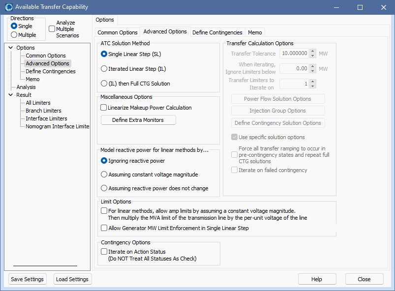
The following parameters can be set on the Advanced Options sub-tab:
ATC Solution Method
One of the solution methods for determining the ATC of a specified transfer direction.
If using either the Iterated Linear Step (IL) or (IL) then Full CTG Solution method, and the seller and buyer are either areas or super areas, and the automatic generation control method for the case is not set to area/super area control, an error message will be produced and the analysis will not continue. In the ATC analysis, transfers between areas are implemented by adding a transaction between areas which requires them to be on area interchange control in order to meet the ACE requirement. If the case was just switched to this control method without the areas already being on area control, the dispatch for the case could drastically change. The burden is left on the user to ensure that control methods are set up correctly. If the case is not already on area interchange control, but one of the island-based methods, and putting it on area control would drastically change the case, the ATC analysis can still be done between areas if injection groups are created to represent the areas and the analysis is then done using these injection groups as the seller and buyer.
Linearize Makeup Power Calculation
When doing the linear ATC calculations, any contingencies that cause a MW change (e.g. dropping generation or changing load) require makeup power to compensate for the change in MW. When this option is checked, a precalculation is done at the beginning of each linear step calculation that determines the impact of makeup power on line flows. When a particular contingency is processed, the effect of makeup power on all monitored lines will be determined by multiplying the precalculated effect of makeup power on a line by the total amount of makeup power needed for the contingency. This calculation is slightly faster than calculating the impact of the makeup power separately for each contingency, but it will not take into account the fact that larger amounts of required makeup power may cause generators to hit their limits.
Define Extra Monitors
Simulator’s ATC tool determines the maximum amount of MW transfer between the seller and buyer. If you would like to also determine the flow on additional lines or interfaces at the transfer levels determined by the ATC tool, you can utilize Extra Monitors. Click the Define Extra Monitors button to open the ATC Extra Monitors dialog. The flow on the extra monitors will be reported for each transfer limiter determined.
Analyze Multiple Scenarios
Check Analyze Multiple Scenarios to perform ATC Analysis on several scenarios. See ATC Dialog for Multiple Scenarios for more information on Multiple Scenario Analysis.
Model Reactive Power for Linear Methods By…
The linearized methods used in the ATC tool are based only on the changes in real power MW in the system, thus an assumption needs to be made about the reaction of the Mvar flows during the linear calculations. The chosen assumption allows a MW limit to be calculated from the defined MVA limit for use in determining the ATC values. Before applying the option for handling reactive power, the specified MVA limit for a branch is used to determine the starting MVA limit. The Limit Monitoring Settings can cause an adjustment the defined MVA limit based on the Branch Percentage specified. The modified limit that is used in the calculations is then:
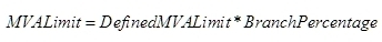
The choices for adjusting the MVA Limit for reactive power are then:
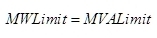
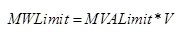
Ignoring reactive power – reactive power is completely ignored. The MW limit of a line is assumed to be the modified MVA limit of the line:
Assuming constant voltage magnitude – reactive power is adjusted to hold voltage magnitudes constant. This option uses the intersection of a branch's operating circle and limiting circle to adjust the limit. The operating circle defines a circle of valid MW and Mvar values for a branch as a transfer takes place across the system. The limiting circle has a radius equal to the modified MVA limit of the branch.
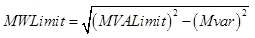
Assuming reactive power does not change – reactive power is held at pre-ATC solution levels. The MW limit for each line is calculated from the MVA limit and the reactive power at the pre-ATC solution level:
For Linear Methods, Allow Amp Limits by Assuming a Constant Voltage Magnitude
If checked, Simulator will allow converting MVA limits to Amp limits by assuming constant voltage magnitudes based on the base case full AC load flow operating point just prior to the ATC linear calculations. This option will only be used if the Limit Monitoring Settings Option of Treat Line Limits as Equivalent Amps is checked.
This option will cause the ATC tool to internally use a modified MVA limit which is equal to the user-specified MVA rating multiplied by the actual terminal voltages of the line. This results in a modified MVA rating which is higher than the user-specified MVA rating when the voltage on the line is higher than nominal and lower when the voltage is lower than nominal. For purposes of calculating the ATC values, a MW limit is determined from the MVA rating based on how this option is set and how the reactive power is modeled.
Ignoring reactive power
Assuming reactive power does not change
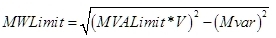
where V is the voltage at the end of the branch from which the limit is taken. The Transfer Limit is calculated at each end of a branch and the most limiting value is reported as the Transfer Limit for a given branch.
Allow Generator MW Limit Enforcement in Single Linear Step
If checked and all of the other relevant options that must be specified to enforce generator MW limits depending on the Seller and Buyer types are set, only generators that are not already at their limits are allowed to participate. For the Seller, generators that are at their maximum limit will not participate. For the Buyer, generators that are at their minimum limit will not participate. If using a injection group for the Seller or Buyer the options to allow only AGC units to vary and not allow negative loads will also be enforced.
This option applies when using the Single Linear Step method either as a standalone method or part of one of the iterated methods. When using the Economic Merit Order Dispatch method with injection groups, limits will be enforced regardless of this option setting provided that all other options necessary to enforce limits are also set appropriately.
Iterate on Action Status (Do NOT Treat All Status As Check)
This option affects how conditional actions are modeled with contingencies when using linear analysis. This is an option is specified with contingency options, but is available here because it impacts the ATC results. See the Contingency Iterated Linear Analysis topic for details.
Transfer Calculation Options
The Transfer Calculation Options section is disabled if the Single Linear Step Solution Method is selected.
Transfer Tolerance
This is the tolerance used during the Iterated Linear Step or (IL) then Full CTG Solution methods. The iterated methods will finish if the transfer step amount for the next iteration is less than this tolerance. The default is 10 MW.
When Iterating, Ignore Limiters below
The iterated techniques perform additional analysis on individual transfer limitations in the order of increasing Transfer Limit in MW. When using one of the iterated techniques, transfer limitations with Transfer Limit values below a certain threshold can be ignored for the iterated portion of the process. Transfer limitations with Transfer Limit values equal to or below the value set with this option may still appear in the results, but they will not be iterated on individually.
Once an individual limiter is being iterated on, this value will no longer be used. This means that during the individual iteration process, the transfer level for a limiter can fall below this threshold.
Transfer Limiters to Iterate on
This is the number of transfer limiters to iterate on in the Iterated Linear Step or (IL) then Full CTG Solution methods. The default is 1. The transfer limiters actually iterated on are determined by selecting the number of limiters set in this option in ascending order of Transfer Limit with the Transfer Limit at or above the value set in the When Iterating, Ignore Limiters below option.
Power Flow Solution Options
This button brings up the Power Flow Solution Options Dialog. This allows the specification of the solution options to use for solving pre-contingency cases and the options used when no contingency-specific solution options are defined. Changing these options affects all power flow computations, even those outside the ATC process.
Because the goal is to stress the system while performing the ATC analysis, there are two power flow solution options that are set internally as part of the ATC process. These are the options that specify the minimum per unit voltage for constant power and constant current loads. These options are both set to 0 pu and override any user-specified settings.
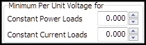
These options are both set to 0 pu during both the base case solution and any contingency case solution.
This button brings up a dialog from which options associated with injection groups can be set. These are the same options that get set for injection groups when using Island-based AGC and dispatching using an injection group except for two additional options; the ATC process switches to using an island-based AGC when iterating and using injection groups for the seller and buyer. The options that can be set are Island AGC Tolerance, Allow only AGC units to vary, Enforce unit MW limits, Do not allow negative loads, and how reactive power load should change as real power load is changed.
The buyer injection group is set as the injection group to use in the dispatch. When implementing the transfer ramping, the source injection group is ramped to the required amount and then the power flow is solved with the buyer injection group picking up any required changes. These changes include adjusting injection in response to change in the seller injection group as well as any changes in losses due to the transfer.
Ramping MethodModified in version 19, build on Aug. 4, 2016
Different ramping methods can be set independently for the Seller and Buyer.
Proportional
The MW output for generators and loads in the injection group will be adjusted in proportion to their specified participation factors. These factors will be normalized for all generators and loads participating in the dispatch. Mvar load will be adjusted according to the options used for setting how reactive power load should change as real power load is ramped.
Economic Merit Order
This method involves dispatching generators so that they are dispatched within an economic range. Details about how economic merit order dispatch is performed can be found under the Generator Economic Merit Order Dispatch topic.
If using this option and an injection group contains ONLY loads, the loads will be adjusted in proportion to their participation factors and economic merit order dispatch will not be used.
Merit Order Close Added in version 19, build on Aug. 4, 2016
This method will dispatch generators in a merit order determined by their specified participation factors. Economic generator limits will be enforced during this process regardless of how the Enforce unit MW limits option is set. Details about this method can be found under the Generator Merit Order Close Dispatch topic.
If using this option and an injection group contains ONLY loads, the loads will be adjusted in proportion to their participation factors and merit order close dispatch will not be used.
During the linear step portion of the iterated methods when using one of the merit order ramping methods, only generators will be included in the linear PTDF calculations. Only online generators in the Buyer injection group will be allowed to participate if the Buyer is using one of the merit order dispatch methods. If the Seller injection group is using one of the merit order dispatch methods, all generators in the injection group will be allowed to participate in the linear calculation as long as they are online or could be energized by closing breakers. When using the proportional method, only online generators in either the Seller or Buyer injection group are allowed to participate.
Injection groups have their own set of options that can override the options on this dialog if they are in use. See the Injection Group Specific Scaling Options topic for more information.
Define Contingency Solution Options
Click this button to open the Contingency Solution Options Dialog. These are the same options that are set with the contingency analysis options.
Use Specific Solution Options
When checked, the ATC tool will use the solution options defined by pressing the Define Contingency Solution Options button for contingency analysis. When not checked, all solutions will use the options defined by pressing the Power Flow Solution Options button.
Regardless of the specific contingency solution option settings, there are two options that will be set internally by the ATC process and will override any user-specified settings. These are the options for minimum per unit voltage for constant power and constant current loads. These options are described in more detail in the Power Flow Solution Options section above.
Force all transfer ramping to occur in pre-contingency states and repeat full CTG solutions
When using the iterated solution methods, the typical iterated operation is to solve for the transfer step amount in the post-contingency state, and then apply the transfer step amount to the post-contingency state and resolve for the next transfer step amount. When this option is checked, the transfer step amount for each iteration is calculated in the post-contingency state, but the power flow state is restored to the pre-contingency state before the transfer step amount is applied. The contingency is then applied after the transfer step amount has been ramped and the transfer step amount for the next iteration is calculated after the contingency has been applied. The purpose of this is to take into account the possibility of conditional actions in the contingency definitions that may not be active in the early steps of the iterated calculations, but may become active at some point during the application of the iterated steps.
Iterate on failed contingency
This option is only enabled when the option to Force all transfer ramping to occur in pre-contingency states and repeat full CTG solutions is selected. When this option is checked and the power flow fails to solve after the contingency has been applied, a new iteration loop is entered to determine the highest transfer level at which the contingency can be solved. This loop attempts to determine a more accurate transfer level at which the contingency fails to solve rather than simply reporting the transfer level at which the last power flow was successful regardless of the current step size. To start the iterative process, the current step size is reduced by half. The ramping is performed and the contingency is solved. The step size will remain the same as long as the contingency can be solved. If the contingency fails to solve, the step size will be reduced by half again. The ramping will continue until the contingency no longer solves, the accumulated transfer during the process meets the original step size, or the step size becomes smaller than the step size tolerance.
An additional check is done during the iterative process on the failed contingency. When the contingency does solve, the flow on the monitored element is checked to determine if it exceeds its limit. If it is overloaded, the step size will be reduced by half until the monitored element is no longer over its limit. While this check is being done on the monitored element limit, the ramping continues out to the specified amount and the contingency is solved.
During the entire iterative process on a failed contingency solution, the step size is limited to be between zero and the step size which was ramped when the contingency failed to solve for the first time.
Tolerances in ATC Tool
When using one of the iterated methods, tolerances must be set correctly with the ATC tool or injection changes will end up being picked up by the system slack instead of the seller and buyer or no injection changes will be made at all. When studying a transfer between injection groups, the Transfer Tolerance will dictate what the MVA Convergence Tolerance, set with the Power Flow Solution Options on the Simulator Options Dialog, and the Island-Based AGC Tolerance can be. Before the analysis starts, the MVA Convergence Tolerance will be checked to make sure that it is less than 0.1*(Transfer Tolerance). If not, the MVA Convergence Tolerance will be set to 0.1*(Transfer Tolerance). The Island-Based AGC Tolerance will also be checked to make sure that it is less than 0.5*(Transfer Tolerance). If not, the Island-Based AGC Tolerance will be set to 0.5*(Transfer Tolerance). The MVA Convergence Tolerance will then be checked to make sure that it is less than 0.2*(Island-Based AGC Tolerance). If not, the MVA Convergence Tolerance will be set to 0.2*(Island-Based AGC Tolerance). This will order the tolerances such that (MVA Convergence Tolerance) < (Island-Based AGC Tolerance) < (Transfer Tolerance). The original tolerances will be restored when the initial state stored with the ATC tool is restored.
When studying a transfer between areas or super areas, there are two AGC tolerances to deal with. These are both checked to make sure that they are less than 0.5*(Transfer Tolerance) and are set to that value if they are not. Both of these tolerances should also be greater than the MVA convergence tolerance. The smaller of the two tolerances in multiplied by 0.2 and the MVA convergence tolerance must be less than this value. If not, the MVA convergence tolerance is set to 0.2*(smaller of the two area/super area AGC tolerances). All tolerances will be restored to their original values when the initial state stored with the ATC tool is restored.