PV Curves Results: Overview
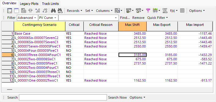
The Overview sub-tab is found on the PV Results tab of the PV Curves dialog. This page provides a summary of all scenarios studied and their results. This table will update as the analysis progresses.
The overview is a case information display and therefore can be used in a manner consistent with all other case information displays.
There are a number of fields that are shown by default on the display:
PV Scenario
Name of the scenario. Either Base Case or the contingency name.
Critical
YES if the scenario is considered to be critical. Otherwise, NO.
Critical Reason
This will be blank as long as the scenario is not critical. If the scenario is critical, there are a number of reasons that could be displayed explaining why the scenario is critical:
Reached Nose - The power flow failed to solve so the system is considered to be at the nose of the PV curve.
Aborted Contingency - The power flow failed to solve because an Abort contingency action was implemented. This indicates that the contingency is simply being skipped at this transfer level without actually trying to solve the power flow.
Inadequate Voltage - The process stopped because at least one voltage is considered inadequate. This reason will only occur when using the option specified on the Limit Violations tab to Stop when voltages become inadequate. The message will be appended with the bus and voltage of the bus with the lowest inadequate voltage.
Inadequate High Voltage - The process stopped because at least one voltage is considered inadequate because it is higher than the high inadequate voltage threshold. This reason will only occur when using the option specified on the Limit Violations tab to Stop when voltages become inadequate. The message will be appended with the bus and voltage of the bus with the highest inadequate voltage.
Source Maxed - The source no longer has enough resources to continue the power transfer. Source resources are affected by the options Enforce unit MW limits and Do not allow negative loads found on the Injection Group Ramping Options sub-tab of the Setup tab. They could also be affected if choosing to use merit order dispatch in which unit limits are always enforced.
Sink Maxed - The sink no longer has enough resources to continue the power transfer. Sink resources are affected by the options Enforce unit MW limits and Do not allow negative loads found on the Injection Group Ramping Options sub-tab of the Setup tab. They could also be affected if choosing to use merit order dispatch in which unit limits are always enforced.
SRT - Indicates that a solvable reverse transfer has been found when choosing to use the reverse transfer option found on the Advanced Options sub-tab of the Setup tab. This message is appended with the original critical reason that required the use of the reverse transfer.
RT Source Maxed - Indicates that the source no longer has enough resources to continue the power transfer when using the reverse transfer option found on the Advanced Options sub-tab of the Setup tab. This message is appended with the original critical reason that required the use of the reverse transfer.
RT Sink Maxed - Indicates that the sink no longer has enough resources to continue the power transfer when using the reverse transfer option found on the Advanced Options sub-tab of the Setup tab. This message is appended with the original critical reason that required the use of the reverse transfer.
Reached Nose in Base Case - This message will only occur for a contingency scenario. It indicates that the contingency scenario is actually less limiting than the base case scenario and that the analysis of the contingency scenario cannot continue because of the base case limitation. The power transfer is always ramped in the base case prior to implementing the contingency. The contingency cannot be attempted unless the base case solves with the transfer implemented.
Negative dV/dQ - Indicates that a critical scenario was encountered due a bus dV/dQ sensitivity being negative. The bus with the most negative dV/dQ sensitivity will be reported.
OPF Cannot be Solved - This indicates that the OPF cannot be solved and will be followed by a message indicating why the OPF cannot be solved. This will most likely be because the power flow could not be solved, i.e. the same as Reached Nose. This is reported when using the Interface MW Flow Ramping Method.
Interface ... Unenforceable- This will contain the name of the interface that cannot be enforced to its specified limit. This is reported when using the Interface MW Flow Ramping Method.
Maximum Transfer- Indicates that a critical scenario was encountered because the Stop when transfer exceeds transfer level is met. Added in version 20, build on January 30, 2018
Branch Violation - At least one branch exceeded a limit when choosing to treat branch violations as critical scenarios. The loading percent and branch at which the largest violation occurred will be reported.
Interface Violation - At least one interface exceeded a limit when choosing to treat interface violations as critical scenarios. The loading percent and interface at which the largest violation occurred will be reported.
Max Shift
This value will only be filled in for critical scenarios. This is the nominal shift that was implemented to reach the critical scenario. The nominal shift is the actual accumulated transfer that was attempted.
Note: With a few exceptions, shift values (includes Max Shift, Max Export, and Max Import) that are reported are from the last solved solution before the critical point was reached. Because the critical point is not considered a valid solution, no valid shift can be determined at this point. Therefore, the values that are reported are as close to this point as the process can get within the tolerances specified for the transfer step size. Exceptions to this occur when using the reverse transfer option. In this case, the values that are reported are for the minimum transfer level at which the contingency will solve and all voltages are adequate. Another exception occurs when a scenario becomes critical because of inadequate voltages at the zero transfer level. Because the scenario can be solved at this point, the shift values will be recorded at the actual step at which the voltages are inadequate. If a case becomes critical due to inadequate voltages and is not at the zero transfer level, the shift values reported for these will follow the rule that they come from the last solved step at which all voltages were adequate. The recording of values determined by Quantities to Track will also follow these same rules.
If a scenario is critical because either the source or sink does not have enough resources to continue the power transfer, the shift values and tracked quantities that are reported are at the maximum transfer level that can be achieved without source and sink limits being violated.
When using the Interface MW Flow Ramping Method, this value is the maximum nominal shift along the search path.
Max Export
This value will only be filled in for critical scenarios. This is the amount that the injection changed in the source injection group due to the transfer and contingency implementation. This value's magnitude can differ from the Max Shift value due to injection changes resulting from make-up power requirements from the contingency.
See note with Max Shift for additional explanation on how shift values are recorded.
This value is only used with the Injection Group Ramping Method.
Max Import
This value will only be filled in for critical scenarios. This is the amount that the injection changes in the sink injection group due to the transfer, loss changes due to the transfer, and contingency implementation. This value's magnitude can differ from the Max Shift value due to the injection changes resulting from make-up power requirements from the contingency and making up for losses due to the transfer. The sink injection group is designated to account for all losses due to the transfer.
See note with Max Shift for additional explanation on how shift values are recorded.
This value is only used with the Injection Group Ramping Method.
Interface X MW Flow, Interface Y MW Flow, and Interface Z MW Flow
These values are reported when using the Interface MW Flow Ramping Method. These are the actual flows on the respective interface at Max Shift.
#Viol, Worst V Viol, Worst V Bus
These fields will be filled when choosing to monitor low or high voltage violations and there are violations for a given scenario. The options to monitor voltage violations are found on the Limit violations tab. These fields give the total number of all bus violations for a scenario, the voltage of the worst violation, and the bus at which the worst violation occurs, respectively. The worst violation is considered to be the one with the lowest voltage.
Max P Mism Bus #, Max P Mism Bus Name, Max MW Mism
These fields will only be filled in for critical scenarios. These give the bus number, bus name, and real power mismatch for the bus with the maximum real power mismatch for the power flow solution at which the scenario becomes critical. For scenarios that are at the nose of the PV curve, the mismatch should reflect the fact that the power flow solution will not converge and might give some insight into problem areas of the system.
Max Q Mism Bus #, Max Q Mism Bus Name, Max Mvar Mism
These fields will only be filled in for critical scenarios. These give the bus number, bus name, and reactive power mismatch for the bus with the maximum reactive power mismatch for the power flow solution at which the scenario becomes critical. For scenarios that are at the nose of the PV curve, the mismatch should reflect the fact that the power flow solution will not converge and might give some insight into problem areas of the system.
The right-click local menu has several options specific to PV results:
Show Dialog
Choosing this option will open the Contingency Definition dialog for the associated scenario's contingency. This dialog can be used to examine the contingency and make any necessary changes.
PV Curve records
There are several PV tool specific options available under this menu item:
Show Violations
This option is available when choosing to monitor low or high voltage violations and there are violations for a given scenario. When monitoring voltage violations, any bus voltages that violate limits will be stored for each scenario at the last studied transfer level. For a given scenario this option will display a table of buses that have voltage violations.
Show Inadequate Voltages
This option is available when choosing to store inadequate low voltages and there are inadequate low voltages for a given scenario. This option will open a table listing any bus that has an inadequate voltage for any transfer level for the given scenario and the voltage for each listed bus at each studied transfer level. If a bus voltage is blank, that means the voltage at that bus was not inadequate for that transfer level.
Show Inadequate High Voltages
This option is available when choosing to store inadequate high voltages and there are inadequate high voltages for a given scenario. This option will open a table listing any bus that has an inadequate high voltage for any transfer level for the given scenario and the voltage for each listed bus at each studied transfer level. If a bus voltage is blank, that means the voltage at that bus was not inadequate for that transfer level.
Show Branch Violations
This option is available when choosing to log branch violations. For a given scenario, this will open a table listing each branch that is a violation at each studied transfer level.
Show Interface Violations
This option is available when choosing to log interface violations. For a given scenario, this will open a table listing each interface that is a violation at each studied transfer level.
Calculated Fields
Calculated fields are available for use with the PV results. The object type that is used for the PV results is PV Curve. This type of calculated field can only be used with PV results. Calculated fields are useful when doing advanced filtering that might involve returning, for example, only the scenario with the lowest inadequate voltage at the lowest inadequate transfer level. Calculated fields are needed to return the lowest inadequate transfer level and then the lowest inadequate voltage that occurs at a transfer level less than or equal to the lowest inadequate transfer level. This type of filtering is needed because it would be possible for inadequate voltages to occur for different scenarios at the same transfer level. The most critical would then be interpreted as the scenario that produces the lowest inadequate voltage.