PV Curves Setup: Interface Ramping Options
Before describing the options used to set up the interface ramping method, the details behind this method are described.
Interface MW Flow Ramping Method
This method is used to modify the flows on selected interfaces along a specified Search Direction. The flows are modified by moving along the Search Direction in specified step sizes. These step sizes are specified with the Common Options. At each step the interface flows are calculated based on the base case flow and the search angle direction. Interface flows are then enforced by solving the OPF algorithm. If the OPF solves, the interface flows are not unenforceable, and the power flow solves, non-critical contingencies are tested at the new nominal transfer level. If a contingency does not solve at a given nominal transfer level, the step size is reduced, new interface flows are determined, and the OPF is solved again to determine the nominal transfer level at which the contingency will be tested again. The reported results provide the highest nominal transfer level at which the OPF algorithm solves, the power flow solves, and all specified interface flows are enforceable.
This method changes how the transfer is modified as part of the PV process. Other inputs to the PV process work the same as they do with the more traditional injection group ramping including Quanitities to Track, Limit Violations, PV Output, and Plots.
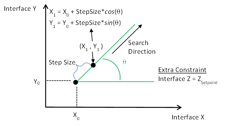
The following image describes the interface ramping method. At a minimum, Interface X must be defined. If this is the only interface defined, the process starts at X0, which is the base case flow on Interface X, and increases the Step Size until a critical point is found. At each step the limit of the interface is increased by the Step Size and the OPF tries to enforce the flow on the interface to this new limit.
If both Interface X and Y are defined, an Angle must also be defined. This specifies the Search Direction. The process starts at X0, Y0, which is the base case flow for both Interface X and Interface Y, and increase the Step Size along the Search Direction until a critical point is found. At each step, the new values for the limits of Interface X and Interface Y are determined base on the distance along the Search Direction and the Angle. The OPF tires to enforce the flows on both interfaces to these new limits.
An optional third Interface Z can be defined. If this is defined, a single MW Setpoint for the flow on this interface must be specified. The ramping process is the same as described above ramping for either Interface X or Interface X and Interface Y, except now the OPF tries to enforce the flow on Interface Z to the same setpoint at each step.
Interface Ramping Options
These options are found at the top of Setup tab found on the PV Curves dialog and the Interface Group Ramping Options tab of the same dialog. The remainder of the setup options for interface ramping are found on the Common Options sub-tab.
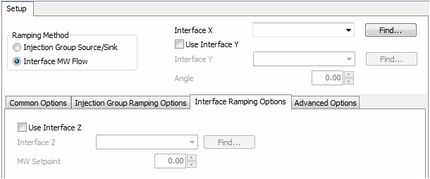
Interface X
Select the name of the interface from the dropdown or click the Find button to use the Choose an Interface dialog to find the interface.
Use Interface Y
Check this box to define Interface Y.
Interface Y
Select the name of the interface from the dropdown or click the Find button to use the Choose an Interface dialog to find the interface.
Angle
An angle in degrees must be entered to specify the Search Direction as described in the Interface MW Flow Ramping Method section. An angle of zero means to increase only Interface X, an angle of 45 degrees means to increase each interface equally, and an angle of 90 degrees means to only increase Interface Y.
Use Interface Z
Check this box to define Interface Z.
Interface Z
Select the name of the interface from the dropdown or click the Find button to use the Choose an Interface dialog to find the interface.
MW Setpoint
Specify the MW flow that should be maintained on Interface Z during the ramping process.
OPF Setup for Interface Ramping
Several options can be set by the user to ensure that the OPF algorithm works as intended:
- OPF Common Options
- Minimum Control Change Objective Function is the suggested option although costs can be defined to mimic a minimum control change algorithm and to allow better control over specific generators and loads
- OPF Control Options
- OPF Advanced Options
- OPF Constraint Options
- Interface Percent Correction Tolerance
- Interface MW Auto Release Percentage
- Interface Maximum Violation Cost
- All other options set automatically by the PV tool
- Generator participation - which ones are on AGC control plus minimum and maximum limits
- Load participation - which ones are on AGC control plus minimum and maximum limits
- Specify the Areas or Super Areas that are on OPF control
Several options are set automatically by the PV tool to ensure that interfaces are enforced correctly:
- OPF Constraint Options
- Only interface constraints will be enabled
- Only interfaces selected in the PV setup are monitored
- Interfaces are enforced with equality constraints
- Interface limits that are enforced
- Contingent interface elements will always be ignored