PV Curves Setup: Common Options
These options are located the Common Options sub-tab found on the Setup tab of the PV Curves dialog. These are the options most commonly adjusted for the PV analysis.
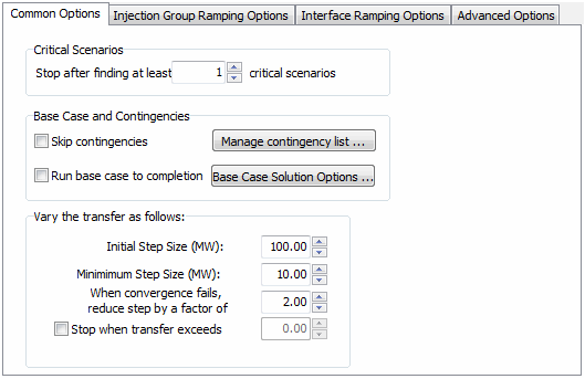
Stop after finding at least ... critical scenarios
A large number of contingencies can be specified for analysis. Usually, there is only concern with determining a certain number of the most critical scenarios instead of running each scenario to its critical point. Set this number to stop the analysis of all scenarios once the specified number of critical scenarios has been found. It should be noted that this number really serves to find at least the specified number of critical scenarios. Depending on when a scenario becomes critical in the process, it is possible that more than the specified number of critical scenarios will be found.
Before implementing a new transfer step for all contingencies, the number of scenarios that are already critical is checked against the number of critical scenarios to find. If at that point the number found is greater than or equal to the number specified, the process will stop. At each transfer step, all contingencies that are not already critical are implemented and a power flow solution is attempted for each contingency. If any contingency does not solve, that contingency is evaluated independently to determine the transfer level at which it becomes critical. If multiple contingencies cannot be solved at a particular transfer step, all of these contingencies will be evaluated independently to determine the transfer level at which it becomes critical. All contingencies are evaluated even if this would cause the number of critical scenarios found to exceed the specified number of critical scenarios to find.
Skip contingencies
The PV Curve tool computes PV curves for both the base topology and for any contingencies that have been defined, unless the Skip contingencies checkbox is checked. If the Skip contingencies checkbox is checked, a PV curve will be computed only for the model in its present (base case) topology.
Manage contingency list…
Clicking this button will open the contingency analysis dialog for managing or inserting contingencies to be processed during the PV analysis. Contingencies defined and marked for processing in the contingency analysis dialog will be included. Only those contingencies whose Skip field is set to NO will be included in the PV analysis.
Note: The Robust Solution Process option that can be utilized with the contingency analysis when a contingency solution failure occurs is not applied when a contingency is implemented during the PV analysis. Most other options defined with contingency analysis such as contingency specific solution options and make-up power specifications are used when applying a contingency during the PV analysis. The exception here is for the contingency-specific solution option for Minimum Per Unit Voltage for Constant Power Load. This is always set to 0 pu during the PV analysis. Also, Model Conditions and Filters that are part of contingency model criteria used during PV and QV analysis allow the use of the Model Condition option to Disable if Condition is True in Contingency Reference State.
Run base case to completion
The PV curve tool is designed to ramp a transfer until the prescribed number of critical scenarios, including both critical contingencies and critical base topology, have been found. If the requested number of critical scenarios have all been identified as being associated with contingencies, the tool will not reveal how much a transfer can be ramped for the base topology, unless the Run base case to completion checkbox is checked. Checking this checkbox forces the tool to continue to ramp the transfer until the base case can no longer be solved, regardless of whether the requested number of critical transfer level / topology combinations have been found.
If using the Stop when transfer exceeds option, it is possible that the base case will not be run to completion if the specified transfer level is exceeded before the critical point for the base case is found.
Base Case Solution Options …
Click this button to bring up the Simulator Options Dialog. This allows the specification of the solution options to use for solving pre-contingency cases and the options used when no contingency-specific solution options are defined. Changing these options affect all power flow computations, even those outside the PV process.
Because the goal is to stress the system while performing the PV analysis, there are two power flow solution options that are set internally as part of the PV process. These are the options that specify the minimum per unit voltage for constant power and constant current loads. These options are both set to 0 pu and override any user-specified settings.
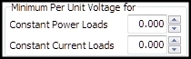
These options are both set to 0 pu during both the base case solution and any contingency case solution.
Initial Step Size (MW)
This option indicates the initial increment in which the transfer will be increased following each successful iteration. The default value is 100 MW.
Minimum Step Size (MW)
Whenever the PV process fails to solve the system at a given transfer level, it will return to the previously solved transfer level, reduce the step size by the specified factor, and then try to solve the system with the transfer incremented by the newly reduced step size. The Minimum Step Size option specifies the minimum size this increment can be. Once the system fails to solve when the step size is at this value, the process will conclude that we have come very close to the voltage collapse point and terminate the analysis. So, the minimum step size essentially functions as a tolerance for computing the voltage collapse point. The default value is 10 MW. The minimum step size must be greater than or equal to 0.1 MW.
See the topic below about Tolerances in PV Tool for more information about how the minimum step size interacts with the Island-Based AGC Tolerance and power flow MVA Convergence Tolerance.
When convergence fails, reduce step by a factor of…
Whenever the PV process fails to solve the system at a given transfer level, it will reduce the transfer step size by the value specified for this option. The default value is 2. Therefore, the process will start incrementing the transfer in 100 MW steps. When it reaches a transfer level that it cannot solve, it will return to the last solved transfer level, reduce the step size to 50 MW, increment the transfer by 50 MW, and attempt to solve the case again. The next time it fails to solve, it will reduce the step size to 25 MW, and then to 12.5 MW, and finally to 6.25 MW. Since 6.25 MW is less than the Minimum Step Size value of 10 MW, it will instead use a final step size of 10 MW. Once the system fails to converge with this step size, the analysis will terminate because it concludes that it has arrived at the voltage collapse point, within the specified tolerance. This value must be greater than or equal to 1.01.
Stop when transfer exceeds
Check this box to terminate the PV analysis once the transfer between the source and sink reaches an amount equal to the MW value specified.
Added in version 20, build on January 30, 2018
When this transfer level is reached, a scenario will be reported as critical.
Tolerances in PV Tool
Tolerances must be set correctly with the PV tool or injection changes will end up being picked up by the system slack instead of the sink injection group or no injection changes will be made at all. The Minimum Step Size will dictate what the MVA Convergence Tolerance, set with the Power Flow Solution Options on the Simulator Options Dialog, and the Island-Based AGC Tolerance can be. Before the analysis starts, the MVA Convergence Tolerance will be checked to make sure that it is less than 0.1*(Minimum Step Size). If not, the MVA Convergence Tolerance will be set to 0.1*(Minimum Step Size). The Island-Based AGC Tolerance will also be checked to make sure that it is less than 0.5*(Minimum Step Size). If not, the Island-Based AGC Tolerance will be set to 0.5*(Minimum Step Size). The MVA Convergence Tolerance will then be checked to make sure that it is less than 0.2*(Island-Based AGC Tolerance). If not, the MVA Convergence Tolerance will be set to 0.2*(Island-Based AGC Tolerance). This will order the tolerances such that (MVA Convergence Tolerance) < (Island-Based AGC Tolerance) < (Minimum Step Size). The original tolerances will be restored when the initial state stored with the PV tool is restored.
Another issue dealing with tolerances is cumulative system slack error. The cumulative system slack error will be recorded after each ramping step. This is done so that an attempt can be made to keep the system slack from deviating more than the Island-Based AGC Tolerance over all of the ramping by adjusting for this error during the next ramping step. This error will be applied to the amount of change required from the sink injection group in an attempt to bring the system slack back towards its original output. Without this accounting it is possible that the system slack could move by the Island-Based AGC Tolerance at each ramping step, and the overall results would be that the system slack could move (Island-Based AGC Tolerance) * (Number of ramping steps) by the completion of the process. With this accounting, the system slack may move up and down slightly over the course of all ramping, but on average will stay near its starting output within the Island-Based AGC Tolerance.