Quick Insert Ribbon Group
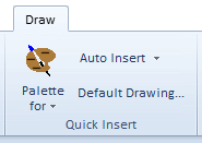
The Quick Insert ribbon group contains buttons for creating a oneline diagram for a system model you have already read into Simulator. If you are building out your network (or even substation, area, or zone diagram), then using the Insert Palettes along with the Auto Insert routines is most efficient. If you would instead like help on inserting a single object on your oneline diagram see the Individual Insert ribbon group topic. Both of the ribbon groups are on the Draw ribbon tab. The Quick Insert ribbon group is shown as follows.


|
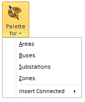
Palette for Menu Choosing any of the first four items in the Show Insert Palette for Menu will open up its respective Insert Palette. This Insert palettes show a list of all objects that are already shown on the oneline diagram as well as a list of objects which are not. For more information see the Using the Insert Palettes help topic. The Insert Connected option will be enabled if a single bus object is selected on the oneline. This submenu provides options to automatically insert any buses not already shown on the oneline that are connected to the selected bus. Additional options allow inserting the connected buses along with connected transmission lines or inserting connected buses along with connected transmission lines, generators, loads, and shunts. |

|
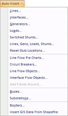
Auto Insert Menu The first six options are used to automatically insert network display objects that are connected to bus objects that have already been drawn on the oneline. Lines : Shows the Automatically Insert Lines Dialog Interfaces : Shows the Automatically Insert Interfaces Dialog Generators : Shows the Automatically Insert Generators Dialog Loads : Shows the Automatically Insert Loads Dialog Switched Shunts : Shows the Automatically Insert Switched Shunts Dialog Lines, Gens, Loads, Shunts : Shows a dialog for auto-inserting lines, generators, loads, and shunts simultaneously. Reset Stub Locations : Will completely redo the positioning of objects anchored to buses and substations in the manner done when auto-inserting lines, gens, load, and switched shunts.
The next four options provide methods for adding pie charts, fields, circuit breakers and line flow objects around objects that have already been drawn on the oneline diagram. Line Flow Pie Charts : Select this to automatically insert line flow pie charts on the transmission lines or transformers objects that are selected. Circuit Breakers : Select this to automatically insert circuit breakers on the transmission lines or transformers objects that are selected. Line Flow Objects : Select this option to automatically insert line flow objects on the transmission lines or transformers objects that are selected. Interface Flow Objects : Select this option to automatically insert Interface flow objects on the interface objects. The Interface Flow Arrow Object which behaves very similar to the Line Flow Object show an arrow to represent the MW flow direction and then shown text for MW value and Mvar value with a sign relative to the MW flow direction. Add Fields Around : Select this option to insert fields around the presently selected objects. It will then bring up the Inserting and Placing Multiple Display Objects Dialog
The follow two options provide a mechanism for auto-inserting bus or substation oneline objects. You must have geographic longitude/latitude information in order to use these options. Buses : Shows the Automatically Insert Buses Dialog Substations : Shows the Automatically Insert Substations Dialog
The last two options provide a mechanism for inserting background lines that represent geographic borders or from a Shapefile. Borders : Shows the Automatically Insert Borders Dialog Insert GIS Data From Shapefile : Shows the Shapefile Import Dialog |