Fixed Number Bus (FixedNumBus) Features
The concepts of SuperBus and Subnet has been in PowerWorld Simulator since 2006. The concept of FixedNumBus was added in Version 24
What is a Bus? This is a fundamental concept that all power engineers feel like we know, but when defining it precisely, it becomes less clear. Many network objects in our power system model are a physical device that is easy to define: transformers and series capacitors for example. An engineer can walk into a substation and point at the device. Transmission lines get more complicated, but they still represent a piece of equipment. The concept of a bus however does not represent a physical device, and depending on the software tool or the engineer using the word "bus" they may mean either (1) a singular point where devices connect to each another, (2) a group of points that share a voltage phasor in a software calculation, or (3) a user defined group of points that may represent several voltage phasors. That is at least 3 different concepts being tied to the same word. Only the singular point concept has some tie to the physical world and even that is not easily described as you will see below. All of these concepts are abstract concepts used by software toola and if you compare multiple software tools you will find that they use the same word "Bus" to describe different concepts.
In PowerWorld there have 4 different objects that are related to these concepts and they are as follows
Bus (a singular connection point)
A Bus defines the physical location where other devices connect to the power system. Load, generator, and switched shunt objects in the power system model have a terminal bus at which they are connected. In addition they have a voltage regulation point which is defined as a bus. AC branch devices (lines, 2-winding transformers, series caps, breakers, disconnects, etc...) have two terminal buses at which they are connected. 3-winding transformers have 3 terminal buses. A restriction for a bus however is that no single device can have two of its terminals connect to the same bus. A Bus can represent many different things in the physical system: a BusBar inside a substation, the point where disconnect switches connect to transformer bushings, a tap on a transmission tower, and a multitude of others.
A Bus has a unique voltage phasor which is fundamental to the network calculations done. All software tools that model a power system have this concept somewhere in their data structure because this is the unique voltage phasor calculated in these software tools. Energy Management Systems (EMS) software tools often call this concept a Node. When PowerWorld Corporation started working with full-topology models used in EMS system in 2006, we made the choice to continue calling this software object a "Bus" inside PowerWorld Simulator.
SuperBus (group of connection points connected by closed switching or extremely low impedance devices)
SuperBus objects are automatically determined by software. Every time a new branch is defined or a branch status changes from OPEN to CLOSED or from CLOSED to OPEN, the SuperBus objects will be automatically redetermined the next time they are needed.
Branch objects have a field specifying a BranchDeviceType with the choices described in the help topic Integrated Topology Processing: Full-Topology Model. A SuperBus is a group of Buses (connection points) that are connected by other closed AC branches that have an extremely low impedance which include the BranchDeviceTypes Breaker, Load Break Disconnect, Disconnect, ZBR, Fuse, and Ground Disconnect. This leaves only the BranchDeviceTypes Line, Transformer, TransformerWinding, and SeriesCap that are not considered extremely low impedance.
When performing Integrate Topology Processing power flow calculations, each SuperBus will have one voltage phasor calculated and all Buses inside the SuperBus will share the same voltage phasor.
Subnet (group of connection points connected by any switching or extremely low impedance devices)
Subnet objects are automatically determined by software. They are the similar to SuperBus objects, but when automatically determining these groupings the status of the branch is ignored.
FixedNumBus (group of connection points defined by the user) Added in Version 24
Background on creation of a FixedNumBus
Each object in PowerWorld Simulator has a list of key fields which uniquely identify an object within the software data structure. Since the very beginning of power system software a convention has been used which defines the terminal bus integer number for many objects as the key field for those objects. This includes objects such as AC Branch, Gen, Load, Shunt, etc. Thus for a generator for example, the primary key fields are the terminal bus number and an 2-character string ID to uniquely identify multiple generators at the bus. This long ago choice has created a lot of problems for the industry because changing just a single bus number will impact the unique keys of all the devices connected to that bus. Thus changing 1 bus number may impact the keys for 10 more devices: 1 bus that has 2 generators, 1 load, and 7 branches connected to it would break the key fields for 10 devices. This has meant that other data source files such as contingency lists, limit monitoring, oneline diagrams, and more will no longer work when the bus numbers change. In 2001, PowerWorld added the concept of string identifiers called labels which would remain unchanged or fixed even as the terminal bus numbers may change. Our customers who work with EMS system models have used those label identifiers to create contingency lists, monitoring lists, scheduled outage files, linking to SCADA measurements, and oneline diagrams which do not rely on unchanged bus numbers to continue to function as the underlying model topology changes. While we continue to encourage all customers to make use of label identifiers, the PSS/E software platform has added a feature we call a FixedNumBus which creates a distinction between a integer terminal number of a device used as a key field which is a fixed number. This FixedNumBus however can have multiple connection points inside it and thus multiple voltage phasors associated with it.
Assignment of a FixedNumBus
Each bus is assigned a link to a bus that will act as its "Fixed Number Bus" or FixedNumBus. By default, every bus will point to itself and thus use its own bus number. The assignment of the FixedNumBus of a Bus is done by typing an integer in the Bus Field named FixedNumBus, loading an AUX file that assigns this field, or when loading special Substation sections of PSS/E RAW Version 34 and later text files. Before accepting the assignment of a bus to a FixedNumBus, Simulator will require that there are not any Branch objects that connect 2 buses inside the same FixedNumBus. If such an assignment is attempted, PowerWorld will ignore the assignment and a message will be written to the message log.
Also, after assigning a Bus to a new FixedNumBus several changes may be made to the power system model automatically to harmonize the data definitions. All of these changes are done to harmonize the definition of a FixedNumBus inside Simulator and also to ensure it maintains the structure required when writing back out to a PSS/E RAW Version 34 or later text file.
The Bus being assigned will have its NomkV, Substation, Area, Zone, and Owner field chanced to match the values at the FixedNumBus .
In addition when editing these fields at buses that below to a FixedNumBus, the fields at all other buses within the FixedNumBus will be changed to match one another.
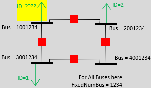
If any Load, Gen, Shunt, Branch objects that are connected to the Bus being assigned will now match the 2-character ID strings of other objects in the FixedNumBus grouping, then 2-character ID strings will be changed so there are not conflicts and a message written to the message log indicating this. The image below shows the constraints on the 2-character IDs.
All buses in the image below are assigned to the same FixedNumBus. When adding the new load boxed in yellow, the ID can not be set to either 1 or 2 because other buses within the FixedNumBus already use this ID.
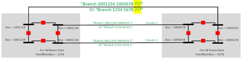
Buses on the left below are assigned to FixedNumBus = 1234 and buses on the right are assigned to FixedNumBus = 5678. Existing branches between these groupings used Circuit 1 and 2. When assigning a new Branch between these groupings the new ID must not be 1 or 2.
SubNodeNum
For supporting PSS/E RAW files, PowerWorld also includes an integer with each bus called a SubNodeNum. In PowerWorld Simulator this integer is not important, but when writing out to a RAW file these integers must be unique for each bus within a substation. When loading a RAW file each bus will be assigned to a FixedNumBus and a SubNodeNum. In the RAW file the SubNodeNum must be between 1-999 and the FixedNumBus must be between 1-999999. To make things reproducible when reading RAW files PowerWorld reads both these values and then creates a bus number equal to 1000000*SubNodeNum + FixedNumBus (except when the SubNodeNum is 1 in which case the bus number is simply FixedNumBus).
Uses of FixedNumBus
The FixedNumBus designations impact how a user interacts with the power system model several locations.
Visualization of Bus, Subnet, SuperBus and FixedNumBus
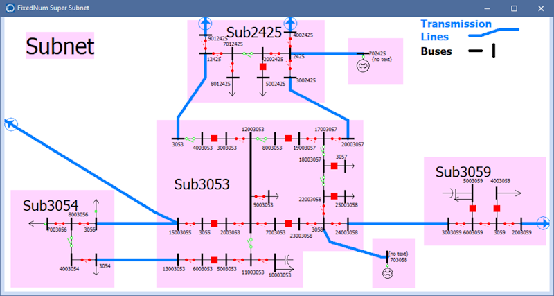
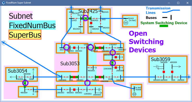
An example system with these concepts visualized is shown below. Each black line segment represents a Bus in PowerWorld Simulator. The groupings of buses are then represented by different colored regions with Subnet in pink, SuperBus in yellow, and FixedNumBus in blue.
|
Each pink region represents a Subnet. These grouping are automatically determined by PowerWorld. In this example, we are only showing buses at a single nominal voltage level so the Subnet designation is the same as a Substation. All objects in the Subnet are connected by extremely low impedance branches or switching devices. All connections between a Subnet will be either Transmission Line, Transformer, Series Cap, or TransformerWinding (of a 3-winding transformer) |
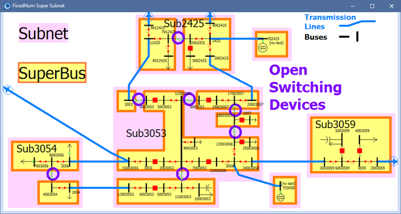
Each yellow region represents a SuperBus. These grouping are automatically determined by PowerWorld. A SuperBus will always be contained inside of a single Subnet. The connections between SuperBus objects inside the same Subnet will be open switching devices denoted in the image below by purple circles.
|
|
|
|
|
Each blue region represents a FixedNumBus grouping. These grouping are user-specified. They will normally be inside the same Subnet and all buses inside a FixedNumBus grouping will normally be connected to each other, and we would recommend that, but that is not required. In PowerWorld Simulator there is nothing different about the switching devices that connect between two FixedNumBus within the same substation, but within the PSS/E format these in a special section of the RAW file called the "System Switching Devices. See the help topic on FixedNumBus and RAW Format for more information. |
The image below here is showing both the FixedNumBus and the SuperBus groupings. Each orange outline represents the SuperBus groupings and you will notice the open switching devices connecting them. Each blue region respresents the FixedNumBus groupings. This is image is here to emphasize that a SuperBus and FixedNumBus are not the same thing. |
|
|