FixedNum Bus and RAW Format
Support for this was added in Version 24. In Simulator Version 23 we could read these files, but we would not maintain the FixedNumBus structures in Simulator and the nodes inside substation would be assigned an unused number.
There are some fundamental data structure differences between PowerWorld's data structure and the structure described in the RAW file format. For example, Substation objects in PowerWorld Simulator have no bearing on the existing of full topology models. Substation objects have existed in PowerWorld Simulator since about 2000 and a Substation is purely a grouping of Bus objects. You can create substations for your entire system model and assign each bus to a substation even in a case that does not model any switching devices. In the RAW file data structure however, the existance of a substation is intertwined with the concept of topology and nodes. A general summary of the structure
|
PowerWorld Simulator |
RAW file data structure |
|
|
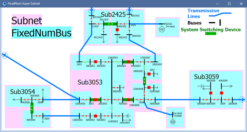
As an example, consider the system topology depicted in the following image
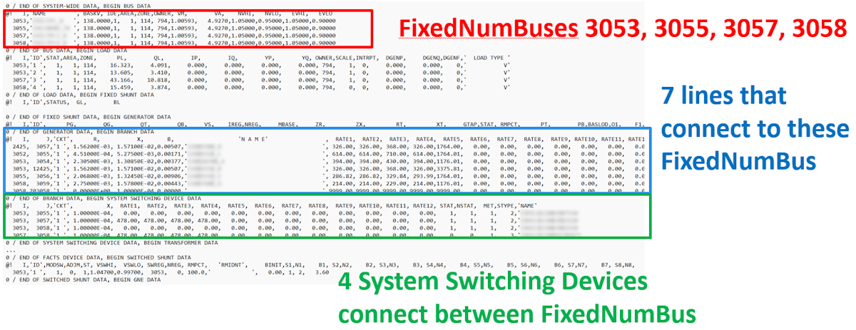
RAW File Top portion for PSSE_Bus, Branch, System Switching Devices
Below is a concentration of only Substation 3053 which is represented in the RAW file data structure. The top portion of the RAW file contains the following
-
4 PSSE_Bus objects number 3053, 3055, 3057 and 3058 (highlighted in red below)
-
7 Branch objects which represent transmission lines between these PSSE_Bus objects (highlighted in blue below)
-
4 System Switching Devices that represent ZBR, Breaker, or Disconnect (highlighted in green below)
One Substation section at the bottom of a RAW file
At the bottom of the RAW file is then a section for Substation and then the Substation Nodes, Switching Devices and Terminal Data.
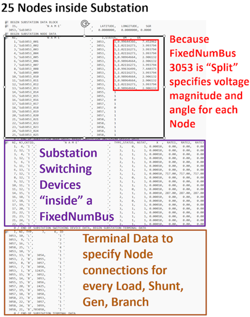
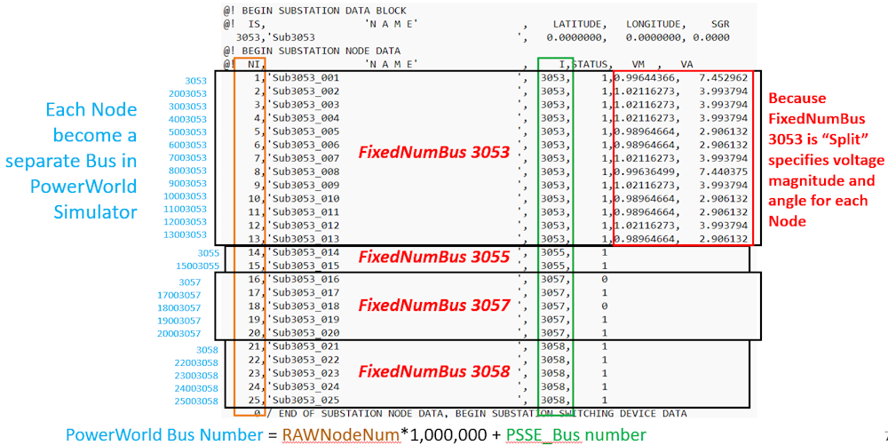
Substation Node Data
A close-up of the Substation Node Data is shown next and illustrates how some of the PSSE_Bus objects have been split into different electrical points and thus must include the voltage and angle in their definition. It also illustrates how PowerWorld assigned a bus number equal to
PowerWorld Bus Number = SubNodeNum * 1000000 + FixedBusNus.
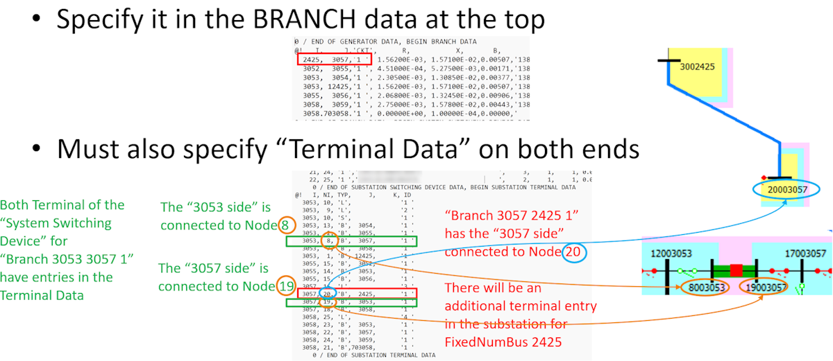
Substation Terminal Data