Load Characteristic Model: CIM5_PTR
 AutoCorrection Properties
Following checks and corrections are applied during Validation and AutoCorrection.
- R1: 1) If motor is not Double Cage or Type 1, then if circuit parameters result in a Tp time constant which is too small then set R1 to a multiple of Tp/(Minimum time constant size as a multiple of time step). 2) If motor is Double Cage or type 2, then if circuit parameters result in a Tpp time constant which is too small then change the motor to single cage by setting R2 and X2 to zero only if Tpp is less than Half the Minimum time constant size as a multiple of time step, and if not just set R1 to a multiple of Tpp/(Minimum time constant size as a multiple of time step).
- R2: 1) If motor is Double Cage and Type 1, then if circuit parameters result in a Tpp time constant which is too small then change the motor to single cage by setting R2 and X2 to zero only if Tpp is less than Half the Minimum time constant size as a multiple of time step, and if not just set R2 to a multiple of Tpp/(Minimum time constant size as a multiple of time step). 2) If motor is Double Cage and Type 2, then if circuit parameters result in a Tp time constant which is too small then set R2 to a multiple of Tpp/(Minimum time constant size as a multiple of time step).
Mult represents the user-specified value Minimum time constant size as multiple of time step option on the Validation page of the Transient Stability Dialog
TimeStep represents the integration time step being used as described on TimeStep
Model Equations and/or Block Diagrams
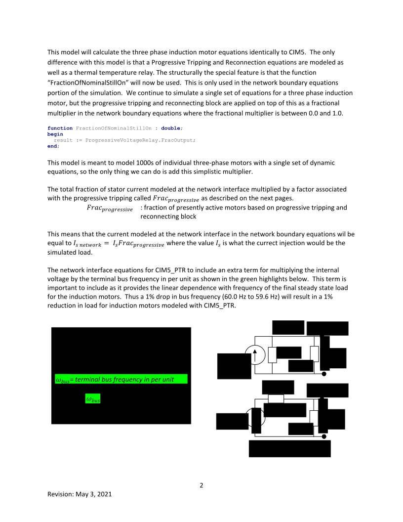
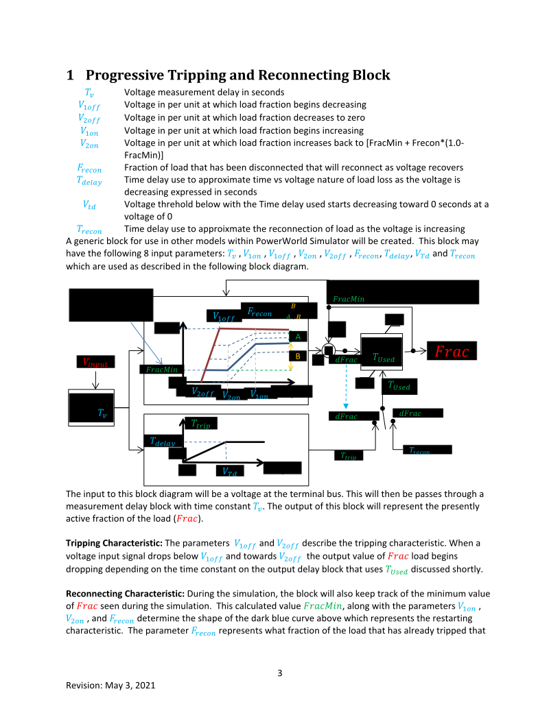
This model builds on the CIM5 model, but makes some modifications
1. Removes the modeling of magnetic saturation.
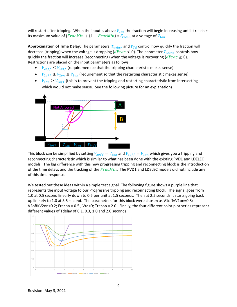
2. Replaces the definite time under voltage relay with a progressing tripping and reconnecting for under voltage model.
3. Modification of the network interface equations to include the impact of terminal frequency
Parameters:
| LF | Load Factor. All values are on an MVABaseUsed=(MW_init)/LF |
| MBase | If MBase > 0 then machine parameters are on this MVABaseUsed is equation to this, otherwise the MVABaseUsed is MWinit/LF |
| Tnom | Nominal load torque used for motor starting studies. For online motors this is automatically calculated from initial conditions. |
| Ra | Armature Resistance in per unit on machine MVABase |
| Xa | Leakage Reactance in per unit on machine MVABase |
| Xm | Magnetizing Reactance in per unit on machine MVABase |
| R1 | Rotor Resistance in per unit on machine MVABase |
| X1 | Rotor Reactance in per unit on machine MVABase |
| R2 | Second Winding Rotor Resistance in per unit on machine MVABase |
| X2 | Second Winding Rotor Reactance in per unit on machine MVABase |
| H | Inertia constant for the motor |
| Etrq | Exponent of the exponential term of the mechanical torque equation T_mech=T_nom (ω_r^(E_trq ) ) |
| Tv | Voltage measurement delay in seconds |
| V1off | Voltage in per unit at which load fraction begins decreasing |
| V2off | Voltage in per unit at which load fraction decreases to zero |
| V1on | Voltage in per unit at which load fraction begins increasing |
| V2on | Voltage in per unit at which load fraction increases back to [FracMin + Frecon*(1.0- FracMin)] |
| Frecon | Fraction of load that has been disconnected that will come back as voltage recovers |
| Tdelay | Time delay use to approximate time vs voltage nature of load loss as the voltage is decreasing expressed in seconds |
| Vtd | Voltage threshold below with the Time delay used starts decreasing toward 0 seconds at a voltage of 0 |
| Trecon | Time delay use to approximate the reconnection of load as the voltage is increasing |
User Parameters
V1off, V2off, V1on, V2on, Frecon
Rules:
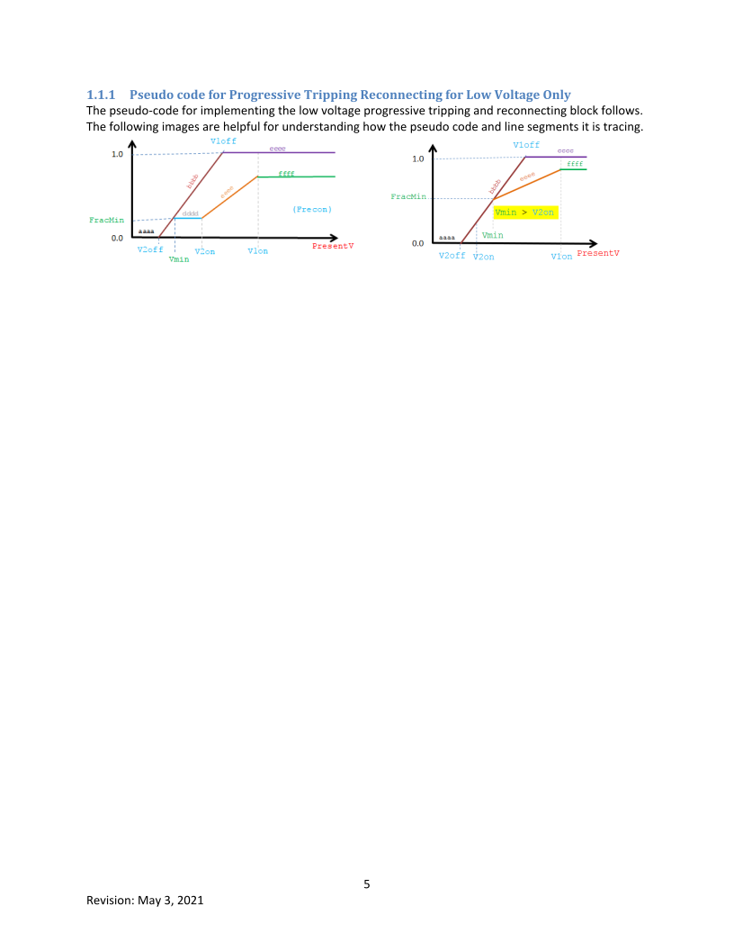
V2off <= V1off
V1on >= V1off
V2off <= V2on <= V1on
Inputs to Block
DelayBlockOutput = output of Time Delay block
PresentV = measured voltage to block
Initialization section does the following
if Frecon < 0.0 then Frecon = 0.0
else if Frecon > 1.0 then Frecon = 1.0
// Order of precedence for trustworthiness of input is V1off, V2off, V2on, then V1on.
if V2off > V1off then V2off = V1off // decrease V2off to at least V1off
if V1on < V1off then V1on = V1off // increase V1on to at least V1off
if V2on < V2off then V2on = V2off // increase V2on to at least V2off
if V1on < V2on then V1on = V2on // increase V1on to at least V2on
Vmin = V1off
FracMin = 1.0
Following updated at the beginning of each Time Step
// FracMin is the minimum fraction during the simulation
if FracMin > DelayBlockOutput < then begin
FracMin = DelayBlockOutput
if FracMin >= 1.0 then Vmin = V1off
else if FracMin <= 0.0 then Vmin = V2off
else Vmin = V2off + FracMin *(V1off – V2off)
end
Following Function for calculating a new DelayBlockInput
if PresentV <= Vmin then begin
if PresentV <= V2off then result = 0.0 // aaaa
else result = (PresentV – V2off)/(V1off – V2off) // bbbb red curve
end
else if (Vmin >= V1off) then result = 1.0 // cccc purple curve
else if (PresentV <= V2on) then result = FracMin // dddd light blue curve
else if (PresentV < V1on) then begin
// see image on right above for situation when Vmin > V2on
if Vmin > V2on then tempV = Vmin
else tempV = V2on
result = FracMin + Frecon*(1.0 - FracMin)*(PresentV - tempV)/(V1on – tempV) // eeee orange
end
else result = FracMin + Frecon*(1.0 - FracMin) // ffff green curve