Power Flow: Voltage Droop Control with Deadband
This is a subtopic of the Power Flow Solution Theory Help. Also see related topics on showing a list of Voltage Droop Control objects or the Voltage Droop Control Dialog.
The ability to use a Voltage Droop Control with Deadband was added in Simulator Version 21
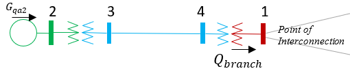
Some generator voltage controls are configured such that the control signals sent to the generator are related to the measurements made at a remote bus instead of the terminal buses. An example of this is renewable generation plants such as a large solar farm or wind generation farm. In a common configuration the power system model for this situation will be as follows.
- All the wind generator or solar inverter are aggregated and modeled as a single generator in the power flow solution (shown at bus 2 in the image below).
- An equivalent transformer stepping up from the low voltage a single wind turbine or solar inverter to the local farm distribution voltage will be modeled (show between bus 2 and 3 in the image below)
- A transformer modeling the transition between the high voltage point of interconnection (bus 1) and the local farm distribution system is modeled (between bus 1 and 4 below)
- An equivalent feeder representing the impedance between the two transformers.
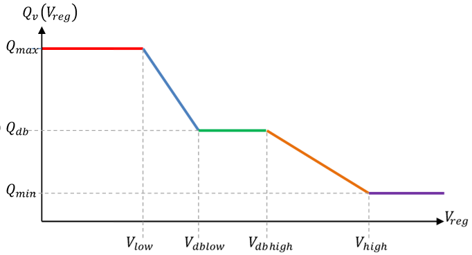
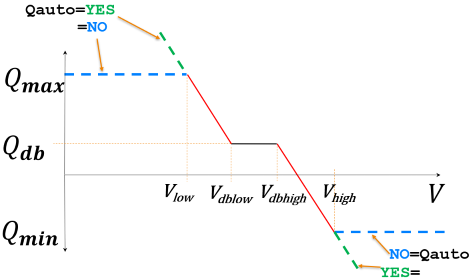
In this configuration, it is common for the renewable generation plant to operate so that at the point of interconnection (bus 1) when the voltage is between Vdblow and Vdbhigh the plant operates at a fixed reactive power output Qdb (often 0.0). Then below the Vdblow threshold the reactive power increases linearly until it is at a specified Qmax at a voltage of Vlow, and above the Vdbhigh threshold the reactive power decreases linearly until it is at a specified Qmin at a voltage of Vhigh. This is depicted in the next image.
This type of voltage control is distinctly different than features such as remote voltage regulation used in other features of the software. They are different because in all other voltage control features the reactive power flows used in the algorithms are the generator Mvar outputs directly. For Voltage Droop Control, the reactive power is the flow arriving at the point of interconnection bus and thus is the reactive flow on the AC branch arriving at Bus 1 and coming from bus 4 shown as Qbranch in the figure above.
When configuring this control in the power flow, the BusCat string will be the following for buses involved.
- PQ (Voltage Droop Reg Bus): this represents the remotely regulated bus of a group of generators that are assigned to the same Voltage Droop Control . The equation at this bus is a special reactive power flow equation ensuring that the droop control curve is enforced. (Bus 1 in picture above)
- PQ (Voltage Droop Remote Bus): this represents on of the remote buses in a group of buses performing voltage droop control. It will enforce an equation then ensures that the total Mvar output of generators at the respective bus is equal to the appropriate proportion of the summation of the Mvar outputs at all generators in the group (click link for more information on Mvar Sharing). (Bus 2 in picture above)
- PQ (Voltage Droop Reg Bus at Var Limit): This is an indication that all the generators that are remotely regulating this bus using voltage droop control are at a Mvar limit. (This could occur at Bus 1 in the picture above).
- PQ (Voltage Droop Remote Bus at Var Limit): This is an indication that a remotely regulating bus in a voltage droop control is at a Mvar limit. (This could be shown at Bus 2 in the picture above).
Determining Grouping of Generators for Voltage Droop Control
If a regulated bus is specified with a VoltageDroopControl object then all generators the are assigned to the VoltageDroopControl will use this regulated bus. (The specification of the regulated bus was added in the Version 21 patch on February 5, 2021.) When a regulated bus is specified with the VoltageDroopControl then there will be one equation associated with the VoltageDroopControl object. Alternatively, if the regulated bus for the VoltageDroopControl is not specified, then Simulator will automatically group together generators that (1) share the same VoltageDroopControl AND (2) regulate the same bus (or buses connected by very low impedance branches that are below the ZBR Threshold and discussed in the advanced power flow options).
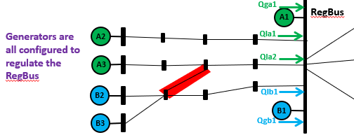
Also note that there can be multiple groups of generators using different VoltageDroopControl objects which regulate the same regulated bus. An example of this would two separate wind farms that ultimately connect to the same regulated bus. This is depicted in the more complex example shown in the following image.
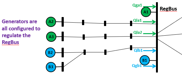
In the example shown in this image, there are two separate VoltageDroopControl objects defined (Green and Blue), however all 6 generators shown regulate the same bus (RegBus). Software tools can easily automatically determine the list of "arriving branches" in this case so PowerWorld automatically determines that Qla1 and Qla2 go with VoltageDroopControl A and Qlb1 goes with VoltageDroopControl B. In addition, it is valid to have some generators in the VoltageDroopControl be located at the RegBus itself as well, so this is automatically detected for generator MVar outpus Qga1 and Qgb1.
The only extra information needed beyond more traditional power flow input data is the specification with each generator at to which VoltageDroopControl it belongs to. The example depicted above may represent two phases of a wind farm project. It is possible that the green generators representing VoltageDroopControl A were added several years ago and are configured under the control of one plant controller (that uses voltage control with a reactive droop). Now a second phase of the wind farm has been install representing VoltageDroopControlB and are controlled using a separate plant controller. Both of these phases connect to the same RegBus and these voltage droop control algorithms will not conflict with one another exactly because the QV characteristic has a negative slope (or "droop"). This is why control system engineers use droop control.
Specification of the QV Characteristic Curve
It may be convenient to express the values of Vlow, Vdblow, Vdbhigh, and Vhigh as deviations away from the voltage setpoints of the generators, so features are given to do this.
It may also be convenient to specify that the Qdb, Qmax, and Qmin values be automatically calculated based on the summation of generator MvarMax and MvarMin, and Qdb is assumed to be 0.0. (If both Qmax and Qmin are the same sign, then Qdb is assumed to be either Qmax or Qmin depending on which value is closer to 0.0. When automatically determine the reactive thresholds for this curve, there is no need to actually enforce those limits in the QV Characteristic curve. Instead we can just rely on the individual generators to enforce their Mvar limits. As a result the QV characteristic curve would change as depicted in the following image. When Qauto is chosen then the red line extrapolates out as shown in the green dashed line.
Handling hitting Generator Mvar limits for Voltage Droop Control
Each generator within the Voltage Droop Control will enforce their own individual Mvar limits. In aggregate there is thus a limitation in the Mvar arriving at the regulated bus from the generators as a result. This is handles in a manner similar to the existing generator Mvar limit checking. The Qmax and Qmin may come into play during the simulation, but it is also possible that all generators in the control will hit a Mvar limit before the solution gets to the Qmax or Qmin level. For example, the following image shows a hypothetical system where the Qmax due to individual generators is shown by the red-dashed line and the Qmin is shown by the green dashed line. In this example, the individual generator MvarMax limits end up above the Qmax characteristic while the individuals MvarMin will end up being hit before reaching the QV characteristic. This is all handled by the software.

Detection of invalid Voltage Droop Control
When implementing Voltage Droop Control algorithms in software it is possible for the user input to present impossible situations. These include situations where there topology between two VoltageDroopControls have an overlapping network. It is not possible to distinguish the Mvars arriving at the regulated bus between the overlapping VoltageDroopControls in this situation, so this is not allowed and the VoltageDroop control would be reported as invalid due to "Overlapping Voltage Droop Networks). The red highlighted line in the following image would represent such an invalid topology.
The user may also specify a topology where it is not possible to reach the regulated bus from the generators in the VoltageDroopControl. This will be reported as invalid due to "Can not reach RegBus".
It is acceptable for there to be generators encompassed by the topology of the VoltageDroopControl as long as those generators are set to AVR=NO. However, if a generator is found that does not belong to a VoltageDroopControl and is configured for either normal voltage control or for LineDrop compensation then this will be considered invalid due to "Conflicting Gen on Voltage Setpoint" or "UseLineDrop= YES for generator".
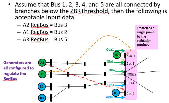
Topology may seem invalid but would not be due to the treatment of the ZBR Threshold
Because of how very low impedance branches are handled in a special manner, it is possible that a topology may appear to have overlapping topologies but will not. The following figure shows a topology that is valid and would be solved with no troubles.
Comments about Detailed Software Implementation
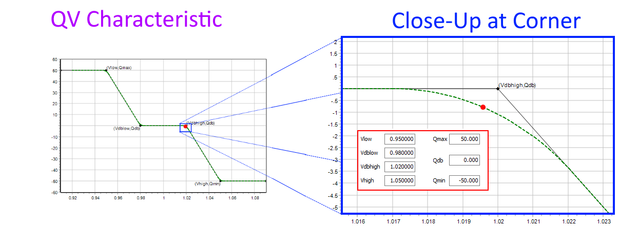
The QV characteristic each user-defined point creates a discontinuous derivative in the QV characteristic. (dQ/dV will suddently change). That will cause a lot of trouble for any iterative solution techniques used to solve a power flow solution. To prevent this from occurring, PowerWorld implements various numerical approximations of the QV characteristic to smooth the transition at these corner points. In addition there are hard-coded restrictions that the voltage transition points must be at least 0.001 per unit (apart) and restrictions on steep the slopes can be on the QV characteristic. You will not notice any of this is going on unless you look very closely at the power flow solution when operating right near these transition points.
Consider the example below. The dashed green line shows what the QV characteristic that is actually being enforced by PowerWorld is, while the black line shows the user-input data. IN this example the Mvar arriving at the regulated bus is about -0.8 Mvar instead of at the user-specified 0.0 Mvar. If you want the extreme details of how this implemented see the equation PDF describing how this is implemented in software.