Power Flow Solution: Advanced Options
The following options are all contained on the Advanced Options tab after choosing the Power Flow Solution page of the Simulator Options.
Dynamically add/remove slack buses as topology is changed
If checked, Simulator dynamically chooses a new slack bus for the islands if the user-input does not adequately define slack buses. If a slack bus can not be determined for an island, the island cannot be solved and will be isolated and ignored during the load flow solution. Also if there are multiple slack buses specified in the same island, Simulator will choose only one of them as the slack bus.
When allowing dynamic slack bus assignment, the choice of the island slack bus is managed in Simulator by internally maintaining a list of buses the user has identified as slack buses while in Edit Mode. Electrical islands are then dynamically determined from the system topology. As branch statuses are changed, this list of islands (and slack buses) will automatically change. For more information about how the islands are created see the help topic on Island Creation. This was made a separate topic in the help documentation in Version 19, build on January 9, 2017
Evaluate Power Flow Solution for Each Island Added in Version 20
Prior to Version 20, Simulator would report a solution as unsolved if any island in the case did not successfully converge to a power flow solution. This meant that if you had a large system with multiple electrical island, then if even one island did not converge the power flow solution would abort. When checking this option, Simulator will abandon solving an island, but continue solving other islands as long as at least one island continues to converge. When choosing this option you will notice messages written to the log about the maximum mismatch in each island as well instead of only the maximum mismatch across the entire case.
Post Power Flow Solution Actions
Clicking this option will open the Post Power Flow Solution Actions dialog, where the user can specify a list of actions to be executed at the end of every full AC power flow solution.
Power Flow (Inner) Loop Options (see Solving the Power Flow for information on solution loops)
Disable Power Flow Optimal Multiplier
If checked, the Newton solution process will not use the optimal multiplier. The optimal multiplier is a mathematically calculated step size for the Newton's Method iteration that prevents the mismatch equations from increasing between iterations. A small value indicates that moving in the direction of the Newton step will increase the mismatch equations. When the optimal multiplier becomes too small, this is an indication that the power flow is not going to solve successfully and Simulator will stop instead of creating extremely large mismatches. If this happens at a point where the solution is not within the allowed tolerance for the Newton process, the Newton process will result in a failed convergence to a valid solution.
Initialize From Flat Start Values
This option only applies to stand alone power flow solutions. Stand alone means a power flow solution initiated by clicking on the Solve Power Flow button on the Power Flow Tools group in the Tools Ribbon Tab. This option does not apply to power flow solution initiated by the contingency analysis, PV Curve, QV Curve, or ATC tools.
When checked, each Power Flow Solution is started assuming that all voltage magnitudes at buses that are not being regulated by a generator or have attached generators are set to unity. If a bus is regulated by a generator or is a generator bus, the voltage magnitude is set to the voltage setpoint of the generator. Voltage angles are set to the voltage angle of the system slack bus. By default, this option is not selected. Some power flow problems can be very difficult to solve from flat start assumptions. Therefore, use this option sparingly.
When the flat start routine is applied to a system which contains many 30 degree phase shifts related to Delta-Wye transformer connections, the flat start routine will set voltage angles in a manner that will handle these phase shifts.
Minimum Per Unit Voltage for Constant Current Loads
This option is used to model the impact that falling voltage has on loads throughout the system. The default value is 0.5.
For constant current loads with a terminal bus below this per unit voltage, the value of the load will fall off using a sine function so that the load is zero at zero terminal voltage, and so that the derivative is continuous at the minimum per unit voltage for constant current loads.
Minimum Per Unit Voltage for Constant Power Loads
This option is used to model the impact that falling voltage has on loads throughout the system. The default value is 0.7.
For constant power loads with a terminal bus below this per unit voltage, the value of the load will fall off using a cosine function so that the load is zero at zero terminal voltage, and so that the derivative is continuous at the minimum per unit voltage for constant current loads.
Control (Middle) Loop Options (see Solving the Power Flow for information on solution loops)
Disable Treating Continuous Switched Shunts (SSs) as PV Buses
Continuous switched shunts are normally treated the same as a generator bus inside the inner power flow loop (they are treated as buses with fixed power and voltage). Checking this option will cause the continuous switched shunt to be treated as a constant impedance in the inner power flow loop with all switch occurring in conjunction with other switched shunts in the voltage control loop instead.
Disable Balancing of Parallel LTC Taps
Simulator has the capability to attempt to balance tap positions of parallel transformers, in an attempt to avoid parallel transformers from going to opposite tap settings, inducing loop flow through the parallel transformers. Checking this option disables the automatic balancing of parallel transformers. The only transformers that will be balanced are those in parallel between the same terminal buses, or those in parallel between terminal buses that are connected with very-low impedance branches.
If enabled, when parallel transformers do not regulate the same bus (actually ZBR Bus group), the transformer will be turned off control automatically and an appropriate message will be written to the log.
When automatically detecting parallel transformers to ensure taps ratios and regulated buses are consistent, the ZBR Threshold user-input parameter is used to determine groupings of buses considered the same electrical point. This ZBR Threshold is also used with generator voltage regulation and making the ZBR Threshold too large can cause numerical problems. Testing has shown that transformer taps and regulated buses for parallel transformers are not as sensitive to this threshold, so a larger threshold is useful so that more parallel transformers can be auto-detected. The impedance threshold used for balancing transformer taps and choosing common regulated buses is 4 times the ZBR Threshold. For example, if ZBR Threshold = 0.00029, then for transformers tap tests we will use a value of 0.00116 instead.
Transformers have an available field called Tap Ratio Change to Balance that provides information about whether or not parallel taps are balanced. When parallel taps are properly balanced, this field is blank. If this field is not blank, the value is the tap ratio that will balance parallel transformers.
Model Phase Shifters as Discrete Controls
If checked, then phase shifters will switch tap positions discretely based on the tap step size of the phase shifting transformer. By default, this option is not checked, which means the phase shifters will switch continuously, independent of the tap step size.
Disabled Transformer Tap Control if Tap Sens. is the Wrong Sign (Normally Check This)
By default if a transformer controls one of its terminal buses, then when performing transformer tap switching calculations, a validation check is done on the sign of the voltage-to-tap sensitivity. If this sensitivity is the incorrect sign, then this indicates that the transformer is operating in an unusual system condition and switching of this transformer is disabled. To disable this default behavior, check this box.
Minimum Sensitivity for LTC Control
This option specifies the minimum-voltage-to-tap sensitivity for LTC transformers. All transformers having an absolute value of voltage-to-tap sensitivity below this value are automatically disabled from automatic control. This prevents Simulator from changing transformer taps that have little effect on their controlling voltage. The Transformer AVR Dialog shows the voltage-to-tap sensitivity for each voltage-controlling transformer.
Disable Angle Smoothing
When a transmission branch status is changed from OPEN to CLOSED across a branch that has a large voltage angle difference, this can introduce a very large initial power flow mismatch and cause the inner power flow loop to diverge. Angle Smoothing will alleviate this large angle difference by smoothing the angles in the system around the newly closed in branch resulting in much better power flow convergence. Angle smoothing will also work if a series of branches are all closed in together. Angle smoothing should be enabled by default, but checking this option will disable this. Angle smoothing works best for individual branches or a series of branches that have been closed that are not electrically near other branches that have been closed. If modifying a case and adding in new transmission lines that are electrically near each other, it might be better for solution convergence to disable angle smoothing.
Disable Angle Rotation Processing
At the end of a power flow solution, by Simulator looks at the bus voltage angles in the case to see if any are near +/- 180 degrees. If the angles fall outside of +/- 160 degrees, then all angles in the island will be rotated by the same amount so that the angle range in the islands is equally spaced around zero degrees. Check this option to disable this feature.
Sharing of generator Vars across groups of buses during remote regulation
When several buses have generators that control the voltage at single bus, this option determines the method used to determine each buses "share" of the MVar support. There are three options
- Allocate across buses using the user-specified remote regulation percentages. This option most closely matches the sharing seen in RAW files. The allocation of Mvars to a bus will be proportional to the average value of the RegFactor for all generators at the bus.
- Allocate so all generators are at same relative point in their [min .. max] var range. This option most closely matches the sharing seen in a few EMS solutions PowerWorld has seen. The RegFactor values are not used with this option, but the MvarMax and MvarMin values will impact the allocation.
- Allocate across buses using the SUM OF user-specified remote regulation percentages. This option most closely matches the sharing seen in EPC files. The allocation of Mvars to a bus will be proportional to the summation of the RegFactor for all generators at the bus.
ZBR Threshold
Added in Version 19
Before Version 19 the ZBR Threshold was 0.0002 per unit always, but can now be changed by the user. The ZBR threshold is used internally in solution algorithms to build groups of buses connected by low impedance branches. Any generator that regulates a bus within these groups will coordinate with other generators when performing voltage control. In addition multiple switched shunts that control buses in the same group automatically coordinate their control. Finally, these groupings are used to find parallel transformers whose tap ratios are then balanced.
PSLF DC Converter Equation Compatibility Options
Use Approximate DC Converter Power Factor Equations (not recommended)Added in Version 22 build on August 20, 2021
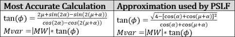
The line-commutated DC Converter equations involve the calculation of the reactive power consumption at a converter using an equation that calculates the tangent of the power factor angle (and thus Q/P ratio) as a function of the firing angle and the overlap angle. There most accurate equation to use for this is shown on the left-hand side of the following image. Testing to obtain the exact same power flow results as PSLF however have shown that an approximate equation as shown on the right below must be used instead (when using this, solutions match exactly). Check the box Use Approximate DC Converter Power Factor Equations (not recommended) in order to use this calculation instead. While not generally recommended, when loading a power flow case from an EPC file, this box is checked to match the treatment in the EPC file.
Use PSLF treatment of Fixed Tap in DC Converters (not recommended)Added in Version 22 build on August 20, 2021
The line commutated DC Converter equations involve the calculation of a TotalTap from VariableTap and a FixedTap. The equations to calculated TotalTap should be {TotalTap = VariableTap + FixedTap - 1}, and all software tools use this equation with AC transformers. However with AC transformers embedded inside the DC converter model only, testing to obtain the exact same power flow results as PSLF have shown that a value of VariableTap*FixedTap must be used instead (when using this, solutions match exactly ). Check the box Use PSLF treatment of Fixed Tap in DC Converters (not recommended) in order to multiply taps in this manner. While not generally recommended, when loading a power flow case from an EPC file, this box is checked to match the treatment in the EPC file.
Include Loss Penalty Factors in ED
If checked, the economic dispatch calculation will consider losses in determining the most economic generation dispatch. Otherwise, the generation dispatch calculation will disregard system losses.
Enforce Convex Cost Curves in ED
The economic dispatch algorithm attempts to set the output of all generators that are set to be automatically controlled so that the system’s load, losses, and interchange are met as economically as possible. The algorithm is guaranteed to reach a unique solution only when all generator cost curves, which model the variation of the cost of operating a unit with its output, are convex. If this option is checked, Simulator will identify units whose operating point is outside the convex portion of the cost curve and set them off automatic control.