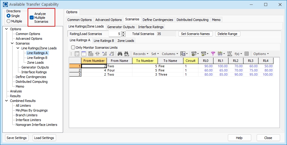
Multiple Scenario ATC Dialog: Scenarios
The Scenarios page of the Multiple Scenario ATC Analysis is available on the Available Transfer Capability Dialog when selecting the option to Analyze Multiple Scenarios on the Advanced Options tab of the Available Transfer Capability dialog.
By defining multiple scenarios, Simulator allows you to calculate ATC values for several different power system states automatically. Scenarios can be modified along three axes:
- Line Rating/Load Scenarios (weather-related scenarios)
- Generation Scenarios (generation profiles)
- Interface constraints
Each of the different scenario types can be defined on its own tab. Each tab contains a list of the power system elements that will be modified during different scenarios. These lists are a familiar Case Information Display providing the same functionality as other displays.
To insert a new power system element into the list, right-click on the list (below the headings) and choose Insert.
If a power system element does not show up in one of the lists of elements for a particular scenario, then it will retain its base case value during that scenario.
When saving or loading scenario elements in an auxiliary file, the elements are usually identified by primary key fields. Optionally, these elements can be identified by label. See the Label topic for more information about this.
Line Ratings/Loads Tab
Use this tab to define Line Ratings, Zone Loads, and InjectionGroup Load scenarios.
Line Ratings, Zone Loads, and InjectionGrup Loads are varied together when analyzing scenarios. This was chosen because they often vary together as a function of the weather. Notice that four sub-tabs (labeled Line Ratings A, Line Ratings B, Zone Loads, and InjectionGroup Loads) appear at the top of the Line Ratings/Loads tab.
Line Ratings A and B
The A rating is typically used as a base case rating, whereas the B limit is typically used as a line rating under contingency. The way line ratings are utilized is defined in Limit Monitoring Settings.
A checkbox, Only Monitor Scenarios Limits, appears on both of these sub-tabs. Check this box to override the normal Limit Monitoring Settings and monitor only the lines that are defined as part of either the Line Ratings A or Line Ratings B lists. When this option is in use, rating A will be used for base case limitations, and rating B will be used for contingency limitations. If a line is not in both lists, the rating that is specified will be used for both base case and contingency limitations. During the ATC calculations, Limit Monitoring Settings will be modified internally to only monitor the specified lines. Once the analysis is complete, the Limit Monitoring Settings will be their original settings.
Zone Loads
The Zones sub-tab has additional options used to specify how Mvar load should vary as the MW load is updated. Only MW load is specified in the scenarios. To specify how the Mvar load should vary, select either Assume Constant Power Factor to have the Mvar load vary with the MW by the same power factor that exists in the base case or No Change in Mvar to keep the Mvar load constant.
When determining how zone loads should be modified during each scenario, the AGC status of each load is used to determine how the MW portion of the load should be modified. For each zone to be modified, the Total MW load for all connected loads in the zone is determined regardless of AGC status. The Total AGC MW load for all connected loads in the zone is determined for only those loads where AGC = YES. If Total AGC MW > 0 then only those loads where AGC = YES will be modified. The multiplier for load changes becomes, multiplier = 1 + (Load MW Change)/(Total AGC MW). If Total AGC MW = 0, all loads in the zone will be modified during the scenario regardless of the AGC status and the multiplier becomes multiplier = 1 + (Load MW Change)/(Total MW). Load MW Change is determined by taking the new MW load value specified with the scenario and subtracting off the Total MW, (Load MW Change) = (New MW Load Value) - (Total MW). If Total MW = 0 meaning that there is presently no connected load in the zone, no load changes will be made. If Total AGC MW > 0, only those loads where AGC = YES that are in-service will be modified with the new MW load at each load becoming the present MW load multiplied by the multiplier (1 + (Load MW Change)/(Total AGC MW)). If Total AGC MW = 0, all loads that are in-service will be modified with the new MW load at each bus becoming the present MW load multiplier by the multiplier (1 + (Load MW Change)/(Total MW)).
InjectionGroup Loads Added in version 24
When scaling by InjectionGroup, only load objects participation points will be scaled. The scaling will be done following the methods described in the Scaling topic under the InjectionGroup heading. The ATC tool will use three fields specified with an InjectionGroup if the InjectionGroup field ScaleOverrideToolOptions = YES. These fields for an InjectionGroup are under the Scale folder in the InjectionGroup list of fields and the parameters important for the ATC tool InjectionGroup Load scaling are as follows
ScaleEnforcePosLoad: Set to YES so that load MWs must always be positive.
ScaleOnlyAGC: Set to YES so that only loads which have a field of AGC=YES will be moved.
ScaleUseConstantPowerFactor: Set to YES to scaled reactive power by the same factor as the real power to maintain a constant power factor.
If the InjectionGroup field ScaleOverrideToolOptions=NO, then the ATC tool option mentioned above for Zone Loads regarding Assume Constant Power Factor or No Change in Mvar will be used to determine how to change Mvars. The choice for OnlyAGC and EnforcePosLoad will obey the options regarding Island-Based AGC on the Power Flow Solution: Island-Based AGC options on the Power Flow Solution page of the Simulator Options.
Creating both Zone Load and InjectionGroup load scenarios that have an overlap in the Load objects is highly discouraged. Also specifying multiple InjectionGroups that have overlapping Load participation points is discouraged. The ATC tool will make no attempt to harmonize these scaling requests and results will be confusing.
Generator Outputs Tab
Use this tab to define scenario changes for generator MW output. Specify a zero output to take a generator off-line. Specifying a non-zero output will force the status of the generator to be closed, meaning that a generator that is currently off-line can be brought on-line during a scenario. The AGC status of a scenario generator will be set to NO so that any changes made via a scenario will not be undone by any automatic generation control schemes. If the bus to which the generator is connected is not in-service, simply changing the generator status to closed will not put the generator in-service. If the case has breakers defined, an attempt will be made to ensure that a generator is truly in-service by closing any open breakers that would cause it to be out-of-service. This is done whenever breakers have been defined in the case. Transmission branches can be identified as breakers by using the Branch Device Type field on the Line and Transformers Display.
Interface Ratings Tab
Use this tab to define scenario changes for interface MW ratings.
Applying Scenarios
When scenarios are applied, all of the changes specified in the scenario are not applied at once. Generator and load changes that cause injection changes will force the power flow to solve if the injection change exceeds a certain threshold. Currently this threshold is 500 MW. Changes will accumulate until this condition is met and then the power flow will be solved. If the power flow fails to converge at any point during this process, the process for making changes for that type of scenario change is aborted, e.g. if there are 10 load changes to be made and accumulated change for the first 5 changes exceeds 500 MW the power flow is solved. If it fails to converge, the changes for the last 5 load changes will not be applied. The system state that remains will not be a state that contains all of the changes for the scenario. Over all scenario types changes are applied in the following order: Line Rating A, Line Rating B, Generator, Load, and Interface. The power flow will only be applied for the changes that affect injection, i.e. generators and loads. If the power flow fails at any step during this process, the remaining changes will not be applied.
The Scenarios page has these additional controls:
Number of Defined Scenarios per Element Type
On each tab, you may enter how many different scenarios should be defined for that kind of power system element. For instance if you set Generation Scenarios to 5, then list display on the Generation Tab will provide 5 columns labeled G0, G1, G2, G3, and G4. Generation outputs should then be entered into each cell representing the generation output in each scenario.
Total Scenarios
Once you have specified the scenarios, Simulator is able to perform ATC Analysis on every combination of the axes. For example, assume you have the following:
- 10 sets of line ratings and zones load
- 8 sets of generation profiles
- 3 interface constraints
This yields a total of 240 different scenarios to calculate (10*8*3 = 240 ). Be warned that the more scenarios you analyze the longer the computation will take.
Set Scenario Names
This button will bring up the Scenario Names dialog, where a different name can be assigned to each scenario.