Auxiliary File Export Format Description (For both Display and Power System)
Definition of an Export Format Description
An export format description consists of the following items:
- A set of object types
- The fields and subdata to be exported for each object type, including how each field should be formatted when written (e.g., number of digits, number of decimal places)
- The format (comma-delimited, space-delimited, etc.) that should be used when writing the object data to disk.
For instance, an export format description might have two object types defined—buses and generators—with indications to export the bus numbers for each of these objects and to write this information to a space-delimited .AUX file.
Types of Export Format Descriptions
Export format descriptions can be defined for both the Display Objects and the Power System Objects,
- Display objects, e.g., background lines, pie charts, displayed fields, etc. Export format descriptions for display objects are defined by selecting Display Objects Export Format Description… on the Onelines ribbon tab, under the List Display Menu on the Active ribbon group.
- Power system objects, e.g., buses, loads, generators, etc. Export format descriptions for power system objects are defined by selecting Power System Objects Export Format Description from the Case Information ribbon tab on the Case Data ribbon group.
The dialogs used to define both types of export format description are very similar; any differences between the two dialogs will be clearly noted below.
Export Format Description Dialog
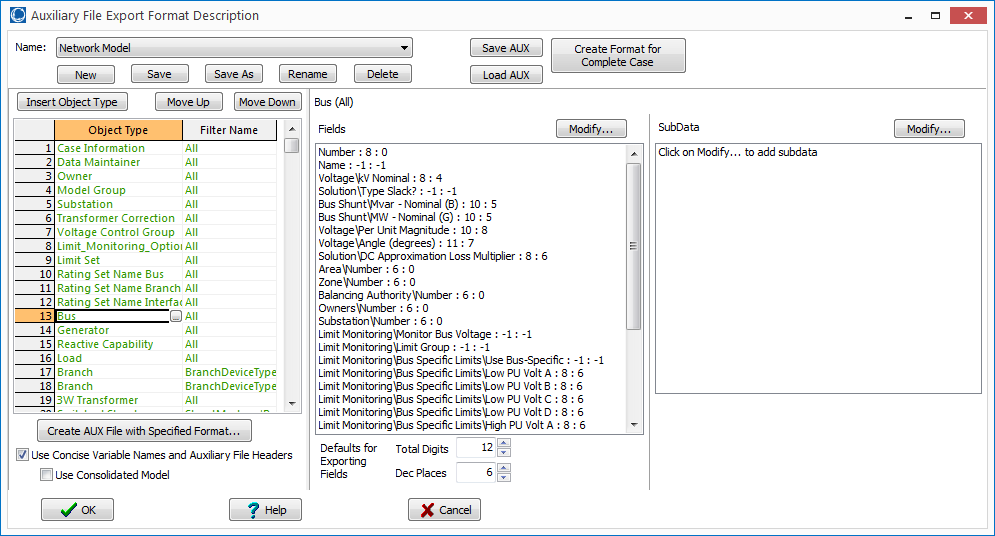
Clicking on Display Objects Export Format Description or Power System Objects Export Format Description, opens the Export Format Description Dialog. There are several buttons at the bottom of the dialog:
- Create Format for Complete Case : click on this button and a drop down will appear giving you the ability to specify hard-coded built-in auxiliary file export format descriptions that define various inputs for PowerWorld Simulator. The various options for input data are described in more detail in Complete Case Auxiliary File Export Format Description. This button will not be available when defining export descriptions for display objects.
- Save AUX : click button to save the list of Auxiliary File Export Format Descriptions to an Auxiliary file.
- Load AUX : click button to load an auxiliary file.
- OK : save the current settings to the selected export format description, and close the dialog
- Create AUX File with Specified Format : writes data to a file using the current settings. A dialog pops up to select the filename for storing the data. If the file already exists, the data is appended; otherwise, a new file will be created. Uncheck the Use Concise Variable Names and Auxiliary File Headers checkbox to use legacy variable names and format for the auxiliary file. If defining an export description for power system data and the ITP add-on is available, the Use Consolidated Model checkbox can be checked to save the consolidated model instead of the full topology model.
- Cancel : do not save the current settings and close the dialog
- Help : open the help associated with the dialog .
The other parts of this dialog box are discussed in detail below
Format Name Section
The uppermost part of the dialog box is used to manage the set of export descriptions. Once one export description has been saved (by clicking Save or Save As, after defining some object types), a drop-down box will appear which allows selection of an export format description from the set of export format descriptions saved with the case: The buttons underneath the drop-down box have the following functions:
- New : clear the rest of the form in order to define a new export format description
- Save : save the information in the rest of the dialog box to the export format description currently selected in the drop-down box. If no export format description is selected, this is equivalent to clicking Save As.
- Save As : save the information in the rest of the dialog box to a new export format description; a dialog will pop-up asking for the name of the new export format description.
- Rename : rename the currently selected export format description
- Delete : delete the currently selected export format description
The list of export format descriptions for display objects and power system objects is kept separate, so the drop-down box will only contain export format descriptions defined for the object type selected from the menu (Display Objects Export Format Description Dialog or Power System Objects Export Format Description Dialog).
Object Type and Filter Method Section
The two-column section on the left side of the dialog box is used to define object types and a filter for each object type.
Object Type
The first column is used to specify which object types are to be exported. To insert a new object type (corresponding to a new row) into the export format description, there are two options—either click the New button above the Object Type column heading, or right click on a row and select Insert. Upon doing this, a dialog will pop up to choose an object type:
Type into the text box to search for a particular object type. The list of object types depends on the type of export description being defined. When defining display object export descriptions, only display object types will show up in this list; similarly, when defining power system export descriptions, only power system objects will show up.
Clicking Choose will insert the object type into the list of object types to be exported.
Double-clicking an existing object type will pop-up this same dialog box, allowing the object type to be changed. Doing so will empty the exported fields, subdata, and filter method.
Filter Method
The second column is used to define an object filter. The default behavior is to export all objects without any filtering, but this can be changed by double-clicking on the filter description. Upon double-clicking on the filter description, a dialog will appear allowing you to choose the filter. The options available for determining which objects are exported are as follows
- All : export all objects, disregarding any filters defined in the current case
- Use Area/Zone/Owner Filter : only export those objects that satisfy the currently defined area/zone/owner filter. Clicking on Select Area/Zone will pop up the dialog box used to define area/zone/owner filters.
- Use Selected : only export those objects that have the Selected field set to Yes. Clicking on Select pop up the dialog box used to set the Selected flag for each of the objects in the case. Note that this particular option does not exist for display objects, because display objects do not currently support the Selected field.
- Meets Filter : only export those objects that meet an advanced filter, which can be either selected from the drop-down box or defined using the Define Filter button.
- When the specified filter only contains a single condition, a prompt will allow storing the single condition as the filter instead of linking to the advanced filter. Using single-condition filters are convenient to use because they do not require that an advanced filter be created and passed along with any aux export descriptions stored in auxiliary files.
Fields And Subdata To Be Exported
After specifying an object type (and, optionally, a filter), selecting the row on the left side of the dialog box will allow you to specify the fields and subdata to be exported.
Fields To Be Exported
By default, no fields are selected for export. To define fields for export, click on the Modify button to the right of the Fields heading the Select Fields dialog box will popup. This dialog is used to specify which fields are to be exported, along with any field-specific formatting of numerical values . Generally the dialog behaves identically to the Configuring Case Information Displays Dialog, so for more detailed help see that topic. There are parts of the dialog that behave differently however, and these are described as follows.
- Total Digits / Dec Places : these two boxes are used to set the number of total digits and the number of decimal places to use when writing the data for the fields current selected in the Selected Fields section. Leaving these two boxes blank means that the default number of digits and decimal places should be used. Also, if multiple fields are selected that have different settings for the number of digits or number of decimal places, these boxes will be grayed out, but still enterable. Once entering a value into either box, all selected fields will then have the same setting, and the box will no longer be greyed out.
Subdata To Be Exported
By default, no subdata is selected to be exported. Also, many objects (e.g., Bus and Area) do not have subdata associated with them, so the Modify button will be greyed out. If an object type does have subdata, then the SubData definition section will be grayed out.
To add subdata that should be exported, click the Modify button to the right of the SubData heading. This brings up the Select SubData dialog. A description of the options/settings on this dialog follows.
- Available SubData : lists the SubData that exist for this object type. If Exclude subdata already selected is checked, then only SubData that is not already in the Selected SubData section will show up in this list.
- Exclude subdata already selected : if checked, then the Available SubData section will only contain items that are not already in the Selected SubData section
- Selected SubData : lists the SubData to be exported for this object type
- Add -> : set the currently selected SubData in the Available SubData section to be exported
- <- Remove : set the currently selected SubData in the Selected SubData section to not be exported
- OK : save the settings and close the dialog
- Save : save the settings, but leave the dialog open
- Cancel : do not save the settings and close the dialog
- Help : click on this to open the help associated with the Select Fields dialog