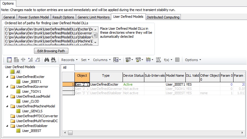
The User Defined Models sub-tab is found on the Options page of the Transient Stability Analysis dialog. The User Defined Models sub-tab shows all information related to the User Defined Models (UDMs) present in the case.

The Edit Browsing Path button tells Simulator the folder(s) to monitor for user defined model DLLs. Simulator automatically populates the rest of the dialog based on the models found. As with built-in models, Simulator keeps track of the model instances that have been inserted.
The User Defined Models panel on the left lists all of the User Defined Model types, as found by Simulator in the browsing path.
The panel on the right is a Case Information Display that changes to show all model instances of the selected type. If All is selected, a summary is shown. If a single model type is selected, a third panel in the bottom right appears and lists specific information for that model.
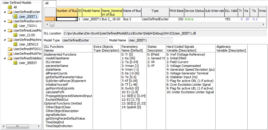
The bottom panel (shown below for a user defined exciter model) contains the DLL location, the model type recognized by Simulator, the model name chosen by the developer, and several lists. DLL Functionsare names of the functions exported by the DLL which depend on the model type. Extra Objects are the object types and descriptions of any other objects whose signals to be used by the model. Parameters are the names and default values of the model parameters. States are the dynamic states of the model.Hard-Coded Signals are the variables which are automatically available to the DLL and change based on the model type. Algebraics are any additional variables required by the model that are not in the hard-coded signals list.
