On the Explore pane on the Model Explorer, there is a folder for Transient Stability. Immediately under this folder is a Summary folder containing links to Generator Model Use, Model Support Status, and Models in Use. These three features are discussed in more detail in the Transient Stability Case Info Menu topic. Under this folder is a list of the various classes of models such as Exciter, Stabilizer, Load Characteristic, etc. which are available in the transient stability tool. When choosing one of these entries, the right portion of the Model Explorer will be populated with a case information display showing models of that class. In addition there will be a new pane showing the specific types of that class of model. This pane has the following attributes
- Gray text indicates a model type which is not presently used by any device in the present power system case
- The number in parenthesis next to the model name indicates the number of models of that type which are used by a device in the present power system case
- Green icons indicate that the model is fully supported by the transient stability numerical integration Simulator.
- Red icons indicate that the model is not supported by the transient stability numerical integration in Simulator. When encountering a new model, PowerWorld will first configure the ability to define the model as well as read and write it from various file formats. After that the model will be implemented. Our intention over time is that all red icons will become green icons.
- At the bottom of the pane is a set of 4 check boxes showing PW only, BPA, PTI, and GE. These indicate which model types to show in the list depending one whether that model is supported by another software package. If you want to see only models which are support by the BPA IPF program then uncheck the other three check boxes and check the BPA check box. For a complete listing of all models and where they are supported see the Summary\Model Support Status in the Model Explorer.
- The list of specific types will always include an entry at the top of All which lists all the models of that class. Below this will be a list of all the specific types of that model class. As you click on the various entries in the pane, the case information display will be populated accordingly.
- At the bottom are buttons to Save or Load dynamic data from an external file.
The following shows such a listing for the generator Exciter models.

All
On the listing which shows all models, there will only be columns which show identifiers for the object as well as two generic columns common to all models. The Fully Supported column is a YES/NO column which shows whether the model is supported by Simulator's transient stability numerical integration (the fast majority will say YES). The Device Status column will show either Active or Not Active depending on whether the device is specified to be used in the numerical integration.
Specific Model Type
When you choose a particular model type, additional columns will appear showing all the input parameters for that model type. This is depicted in the image below.

Show Block Diagram Button
At the top-right of the case information displays listing models will be the Show Block Diagram button. When clicking this button, the BlockDiagrams.pdf Adobe Acrobat file will automatically be opened which contains all the dynamic model block diagrams. This PDF file will automatically be navigated to show the block diagram of the presently selected model in the case information display.
Load Characteristic Models
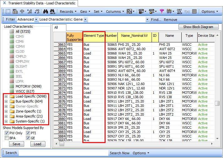
Load models in Simulator are configured to apply to either a load, bus, owner, zone, area, or the entire case. This is discussed in more detail in Transient Stability Overview. As a result you will see special folders at the bottom of the specific model type list for Load-Specific, Bus-Specific, Owner-Specific, Zone-Specific, Area-Specific, and System-Specific.
