QV Curves Options: Solution
These options are found on the Solution sub-tab located on the Options page of the QV Curves dialog.

Default solution parameters
Voltage step size (pu)
Increment between voltage set-points used to trace a QV curve. This is the default value that will be applied to a bus unless a bus-specific value is specified.
Minimum voltage (pu)
Minimum voltage at which the analysis will be performed. This is the default value that will be applied to a bus unless a bus-specific value is specified.
Maximum voltage (pu)
Maximum voltage at which the analysis will be performed. This is the default value that will be applied to a bus unless a bus-specific value is specified.
Use initial voltage as Vmax
Check this box to use the initial voltage at a bus as the maximum voltage at which the analysis will be performed. This option overrides any of the other options that set the maximum voltage for a bus. The initial voltage at a bus is determined prior to starting the QV analysis but after applying contingencies and applying any additional var support necessary to make an unsolvable scenario solvable.
Power flow solution options
Global solution options
Click this button to bring up the Simulator Options Dialog. This allows the specification of the solution options to use for solving pre-contingency cases and the options used when no contingency-specific solution options are defined. Changing these options affect all power flow computations, even those outside the QV process.
The global solution options will be used in the QV analysis unless QV-specific solution options are defined using the option described below. If contingency-specific solution options are defined for a contingency, those options will override both the QV-specific solution options and the global solution options.
QV Power Flow Solution Options
Click this button to bring up a dialog that allows specification of QV-specific power flow solution options. These are the same options that are described in the Simulator Options Dialog for Power Flow Solution Options. The order in which QV-specific solution options are applied relative to the contingency solution options is controlled by the next option.
The option to Dynamically Add/Remove Slack Buses as Topology is Changed (Allow Multiple Islands) is handled in a special manner when applying these options. This option cannot be set to allow multiple islands if it has previously been set to not allow multiple islands. This will be enforced when these options are applied.
When to apply QV Power Flow Solution Options (Added in Version 21, build on January 29, 2021)
The sequence of when to apply the QV Curve power flow solution options is determined by this option. It may be set to either be applied Before or After the contingency (or base case) power flow solutions. Prior to the Version 21, build on January 29, 2021, this option was not available and the QV curve was always processed as though the option was set to Before. If the value is set to Before, then the QV curve options are applied before the contingency solution, and as a result any contingency solution options will override any QV curve options. If the value is set to After, then the QV curve options are applied after the contingency power flow solution and thus the QV options will override any contingency solution options.
The overall process for a particular contingency (or base case) is as follows:
Start with the Global Power Flow Solutions options
If When to Apply = Before, then apply the QV Curve Power Flow Solution Options
Apply the Contingency Power Flow Solution Options (not for the base case)
Solve the power flow for the contingency (or base case)
If When to Apply = After, then apply the QV Curve Power Flow Solution Options
Trace the QV curve by varying the voltage setpoint as desribed in the help topic QV Curves
Because the goal is to stress the system while performing the QV analysis, there are two power flow solution options that are set internally as part of the QV process. These are the options that specify the minimum per unit voltage for constant power and constant current loads. These options are both set to 0 pu and override any user-specified settings.
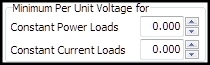
These options are both set to 0 pu during both the base case solution and any contingency case solution.