Power Flow Tools Ribbon Group
The main function of PowerWorld Simulator is to simulate the operation of an interconnected power system. The simulation is accomplished by selecting Solve Power Flow – Newton from either the Quick Access Toolbar or the Power Flow Tools ribbon group on the Tools ribbon tab. This activity performs a single Power Flow Solution. See Solving the Power Flow for more information.
The following tasks are also available from the Power Flow Tools ribbon group on the Tools ribbon tab.

Solve Power Flow – Newton
The main function of PowerWorld Simulator is to simulate the operation of an interconnected power system. The simulation is accomplished by selecting Solve Power Flow – Newton from the Power Flow Tools ribbon group on the Tools ribbon tab. This activity performs a single Power Flow Solution. See Solving the Power Flow for more information. Also note that if presently in Edit Mode, you will be automatically taken to Run Mode when choosing this.
Simulator Options
When choosing any of the solution methods, the options as specified in the Simulator Options will affect what calculation is performed. You can solve the power flow usin either the Full Newton AC load flow or the DC Approximation load flow, as specified in the Simulator Options.
Voltage Conditioning
Added in Version 23
Click this button to open the Voltage Conditioning Dialog
Play Button
Click this button to cause repeated solutions of the system and to cause the animation of oneline diagrams
Pause/Stop Button
Click this button to stop the action of the Play button.
Restore Menu
The Restore menu offers option to either Restoring a Previous Solution or a Restore a Previous State.

Sometimes a power flow attempt won't converge to a solution. When this occurs, the voltages and angles calculated by the solution engine will not satisfy the real and reactive power balance constraints at each bus. The state currently stored in memory will not be an actual system operating point. It is often very difficult to coax the system to solve once it has failed to converge.
To help you recover from a solution attempt that has failed to converge (both timed simulations and single solutions), Simulator offers you two options.
After Simulator solves a system successfully, it will store the voltages and angles it found in memory. If the changes that you then make to the system result in a system that can't be solved, you can select Restore > Last Successful Solution from the Power Flow Tools ribbon group on the Tools ribbon tab to reload the results of the last converged solution. After reloading this information, Simulator will re-solve the system and refresh all displays.
In addition to restoring the last converged solution, Simulator also gives you the ability to restore the state of the system as it was just prior to the unsuccessful solution attempt. This can be thought of as "un-doing" the effect of the solution attempt. Before attempting a solution, Simulator stores the state of the system in memory. If it solves the power flow successfully, Simulator will discard this pre-solution state. However, it the power flow fails to converge, Simulator will keep the state in memory. To recover it, select Restore > State Before Solution Attempt from the Power Flow Tools ribbon group on the Tools ribbon tab. Simulator will replace the non-converged post-solution state with the pre-solution state and refresh the displays. You can then play with the system to try to make it easier to solve.
If you are working with large systems, you should be aware that saving these system states can consume a lot of memory. Therefore, Simulator offers you the option to disable one or both of these features. To do this, select Simulator Options from the Case Options ribbon group on the Options ribbon tab to open the Simulator Options Dialog, and then go to the Storage sub-tab of the Solution tab. You will see two checkboxes there that can be modified to control whether or not these extra system states are saved.
Solve Menu
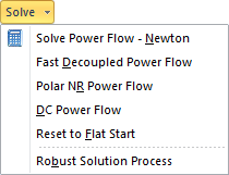
Solve Power Flow – Newton
The main function of PowerWorld Simulator is to simulate the operation of an interconnected power system. The simulation is accomplished by selecting Solve Power Flow – Newton from the Power Flow Tools ribbon group on the Tools ribbon tab, or from the Quick Access Toolbar. This activity performs a single Power Flow Solution. See Solving the Power Flow for more information. Also note that if presently in Edit Mode, you wil be automatically taken to Run Mode when choosing this.
Polar NR Power Flow
This perform a Newton-Raphson power flow solution using polar coordinates instead of rectangular coordinates as is normally done in Simulator.
DC Power Flow
This automatically change the Simulator Options to use the DC Approximation and then immediately performs the DC power flow solution.
Reset to Flat Start
Select Solve > Reset to Flat Start from the Power Flow Tools ribbon group on the Tools ribbon tab to initialize the Power Flow Solution to a "flat start." A flat start sets all the voltage magnitudes to either 1.0 or generator setpoint voltages and all the voltage angles to the system slack angle. Usually, a flat start should be used only if the power flow is having problems converging. You can also use the flat start option on the Simulator Options Dialog to initialize every solution from a flat start.
Robust Solution Process
The Robust Solution Process provides a method to attempt to reach a solution when the standard load flow (Newton-Raphson) solution fails. The robust process performs a solution in a series of steps.
First, the robust solution will turn off all controls in the case. Then the load flow will be solved using a fast decoupled power flow. If the fast decoupled power flow reaches a solution, Simulator then immediately solves the load flow using the Newton-Raphson load flow, still keeping the controls turned off. If the Newton-Raphson solution is also successful, Simulator will begin adding controls back into the solution process, one type of control at a time. Thus the generator MVAR controls are added back in, and the load flow is resolved. Then the switched shunt controls are restored, and the load flow is again resolved. Simulator will continue in this manner by reintroducing next the LTC control, followed by the area interchange control, and lastly the phase shifter control. Furthermore, when reintroducing the phase shifter control, the controls are added one at a time for each phase shifter, with a load flow solution occurring after each.