Nomogram Information Dialog
 See Also
This dialog has the following controls:
Nomogram Name
An alphanumeric identifier for the nomogram.
Interface A
The first interface forming the interface pair. To add the interface from scratch in the nomogram dialog, click on the Insert New Element button. In this manner you will be creating the interface from the individual elements, the same as creating an interface on the interface dialog. If you already have an interface defined, and wish to clone the elements of that interface for this nomogram, use the button labeled Clone Elements From to find the interface and copy the element definition.
Interface B
The second interface forming the interface pair. To add the interface from scratch in the nomogram dialog, click on the Insert New Element button. In this manner you will be creating the interface from the individual elements, the same as creating an interface on the interface dialog. If you already have an interface defined, and wish to clone the elements of that interface for this nomogram, use the button labeled Clone Elements From to find the interface and copy the element definition.
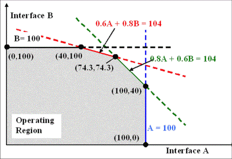
This section is used for defining the limit boundaries for the interface. The limit boundaries are defined by inserting nomogram breakpoints. These breakpoints correspond to a pair of MW flows on each interface. In other words, you define the amount of flow allowed on Interface B when interface A is at a certain amount. Typically you will have a flow limit on Interface B that is constant for a certain range of flow in interface A. However, at some point as the flow on Interface A increases, the limit of flow on Interface B can start to decrease due to desired flow limit restrictions of the combined interfaces. At some point, the limit of Interface A would reach a maximum amount and remain constant, and the range of flow on interface B would be fairly small due to the heavy loading in Interface A.
To build this Nomogram Limiting Boundary, begin by right-clicking in the Nomogram Breakpoints list and choose Insert Point. Note that the boundary definition must be a convex piecewise linear curve. You would typically being by defining the flow limit allowed on Interface B when the flow on interface A is small or zero. Then define breakpoints where the limit on B decreases as the flow on A increases. Eventually you will define a point where the flow on A reaches a limit as the flow on B continues to decrease towards zero. In short, the nomogram limiting boundary is actually a combination of boundary limits that are scaled combinations of the individual interface limits. See the image below for an example of a nomogram limiting boundary.