Geographic Data View
Geographic Data Views allow the quick creation and formatting of graphical representations of buses, generators, loads, switched shunts, transmission lines, substations, areas, zones, super areas, and injection groups. Latitude and longitude coordinates specified with buses and substations are used to place objects geographically on a display. The latitude and longitude coordinates must be specified in order to use this feature. Object attributes such as color, size, rotation rate, rotation angle, and visibility can easily be formatted based on the associated data object field values.
To create a Geographic Data View, open a case information display for the desired element type, select the elements for which to add geographic representations, and either right-click on the object grid and choose Geographic Data View > Geographic Data View from the local menu or choose Geo > Geographic Data View from the case information toolbar. Use the Select Column, then Geographic Data View option to select an entire column of elements. The column in which the elements are selected determines the initial selection of the field to use for attribute settings. The Geographic Data View Customization dialog will open.
Geographic Data View Customization Dialog
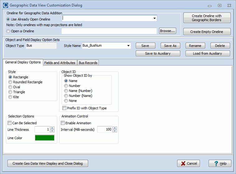
Oneline for Geographic Data Addition
When creating a new geographic data view, the oneline to which to add the geographic data view objects must be set. Choose either to Use Already Open Oneline and then select a oneline from the dropdown list of available onelines or choose to Open a Oneline and then either type in the name of a PWD file or click Browse to select a one.
Because geographic data views are dependent on having geographic latitude and longitude information available, the oneline that is selected must have a valid map projection in use. Only those open onelines that currently have a map projection in use will be listed in the dropdown box and any oneline opened from a file will be checked for a valid map projection. If a valid map projection does not exist, new geographic data view objects will not be added to the oneline.
Create Oneline with Geographic Borders
Click this button to create a new oneline diagram with first being prompted to add geographic borders. A default name will be assigned to the new oneline and that oneline will be added as the selected oneline in the Use Already Open Oneline dropdown.
Setting Attributes for Geographic Data View Display Objects
Before adding new geographic data view objects, the attributes associated with the objects should be set. These attributes are stored in Geographic Data View Styles.
Create Empty Oneline
Click this button to create a new oneline diagram. A default name will be assigned to the new oneline and that oneline will be added as the selected oneline in the Use Already Open Oneline dropdown.
Create Geo Data View Display and Close Dialog
Click this button to accept all of the option settings, add new geographic data view objects to the selected oneline, and then close the dialog.
Cancel
Click this button to close the dialog without adding and new geographic data view objects.