Branch Model: SCMOV
This represents a model of the over-current and over-voltage protection for a series capacitor which uses a Metal Oxide Varistor (MOV) and bypass switch. The model is based on the following paper from 1987.
D. L. Goldsworthy, “A linearized model for MOV-protected series capacitors”, IEEE Transactions on Power Systems, Vol. PWRS-2, No. 4, November 1987
See the Goldsworthy paper for a detailed explanation of this technology. Below is a description of how the model impacts the software simulation.
The Input Parameters for SCMOV are as follows:
|
Icrated |
Capacitor Rated current in Amps |
|
Icappro |
Capacitor protective level current, pu on Icrated base |
|
Ithresh |
Threshold value for MOV activation. |
|
Daccel |
Parameter not used by PowerWorld Simulator |
|
Enerlim |
MOV energy limit in Mjoules |
|
Enerdly |
Bypass delay associated with Enerlim in seconds |
|
Imovlim |
MOV current limit in pu of Icrated |
|
Imovdly |
Bypass delay associated with Imovlim in seconds |
|
Icaplim |
Capacitor current limit in pu of Icrated |
|
Icapdly |
Bypass delay associated with Icaplim in seconds |
|
Operdly |
Parameter is not used by PowerWorld Simulator |
|
Iinsert |
Insertion current in pu of Icrated |
|
Tinsert |
Insertion time in seconds |
|
ImovTup |
Pickup time for the Imovlim in seconds |
|
IcapTup |
Pickup time for the Icaplim in seconds |
Other Output values for SCMOV are as follows
|
Mode |
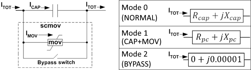
Mode of operation 0 = NORMAL (model impedance as Rcap + jXcap) 1 = CAP+MOV (model impedance as Rpc + jXpc calculated as described below) 2 = BYPASS (model impedance as 0.0000001 + j0.00001 |
|
ItotAmp |
Total current magnitude seen by the network solution in Amps |
|
IcapAmp |
Current magnitude across the capacitor in Amps |
|
ImovAmp |
Current magnitude across the MOV in Amps |
|
EnergyMOV |
Accumulated energy absorbed by the MOV in MegaJoules |
|
Itotpu |
Total current magnitude seen by the network solution in per unit on the system base |
|
Icappu |
Current magnitude across the capacitor in per unit on the system base |
|
Imovpu |
Current magnitude across the MOV in per unit on the system base |
|
Rused |
Rpu (on system base) used in the network algebraic solution |
|
Xused |
Xpu (on system base) used in the network algebraic solution |
SCMOV Three Modes of Operation
The complex currents used when modeling this device are shown in the figure below.
The model operates in three different modes with the treatment in the algebraic network boundary equation solution as follows.
|
Mode |
Treatment in Algebraic Network Boundary Equations |
Currents Reported for Output |
|
NORMAL Mode=0 |
The original Rpu and Xpu of the series capacitor is used to model the device in the algebraic network boundary equations. Note: during a algebraic network boundary equation solution, the device will instantaneously change to Mode 1 (CAP+MOV) if the current threshold Ithresh is exceed as described in the transitions below. This special transition during the algebraic solution is needed to prevent very large current spikes that occur at fault inception on or near the terminals of these series capacitors. |
Itot = magnitude of current through branch
Icap = Itot
Imov = 0.0
|
|
CAP+MOV Mode=1 |
An Rpc + jXpc is calculated as described in the image below based on function of the current Ipux described in the Goldsworthy reference paper. While operating in this mode the energy absorbed by the MOV is calculated by determining the resistance of the equivalent impedance Rpc+jXpc and the branch impedance Rcap+jXcap. This requires solving the following equation for Rmov. (Rmov+jXmov) = 1 / ( 1/(Rpc+jXpc) - 1/(Rcap + jXcap) ) The power absorbed over a time step as resistive loss is calculated as follows MegaWattMOV = (Rmov*Imovpu*Imovpu)*SystemMVABase Integration is approximated by multiplying the TimeStep length in seconds by MegaWattMOV and keeping the accumulated sum as the value EnergyMOV (with units of MegaJoules). Also note that the accumulated EnergyMOV is not reset during the simulation even when transferring out of this mode. Also note that the Goldsworthy paper suggested using the following equation for the power loss which gives the same answer when Rcap = 0. MegaWattMOV = (Rpc*Itotpu*Itotpu)*SystemMVABase |
Itot = magnitude of current through branch
Icap = current calculated from terminal voltage and original Rcap and Xcap
Imov = magnitude of the complex current calculation (Itot - Icap)
|
|
BYPASS Mode=2 |
When operating in Mode 2 (BYPASS) the minimum internal impedance is used of R + jX = 0.0000001 + j0.00001 |
Itot = magnitude of current through branch Icap = 0 Imov = 0 |
Mode Transitions
Transitions between the 3 operating modes can occur as follows with 4 possible transitions as depicted in the next image. The conditions under which these mode transitions occurs are described in the following table.
![]()
|
From Mode |
Transition to Mode |
Description |
|
NORMAL Mode=0 |
CAP+MOV Mode=1 |
When in Mode 0 (NORMLA), at the end of each time step of the simulation if the following condition is met then the device will switch to Mode 1 (CAP+MOV) Ipux > Ithresh , where Ipux = ItotAmp/(Icappro*Icrated) . Note that the current base for getting Ipux in per unit is different than the per unit for comparisons to Icaplim and Imovlim described later because the multiplier Icappro is used with Ipux. During an algebraic network boundary equation solution, the device will instantaneously switch to Mode 1 (CAP+MOV) if the current threshold Ithresh is exceed as described in Mode 1 description. If this occurs the mode is switched and the algebraic solution is immediately redone. |
|
NORMAL Mode=0 |
BYPASS Mode=2 |
This direct transition will not happen |
|
CAP+MOV Mode=1 |
NORMAL Mode=0 |
When in Mode 1 (CAP+MOV), at the end of each time step, if Ipux <= Ithreshthen the device transitions to Mode 0 (NORMAL) for the next time step. |
|
CAP+MOV Mode=1 |
BYPASS Mode=2 |
When in Mode 1 (CAP+MOV), at the end of each time step, three different checks are done to determine if a transition to Mode 2 (BYPASS) is made.
|
|
BYPASS Mode=2 |
NORMAL Mode=0 |
When in Mode 2 (BYPASS), the model allows for reinsertion of the device if the bypass decision was made due to the Imovlim or the Icaplim. Reinsertion will occur if all other bypass conditions are not met and the current is below the Iinsert for Tinsert seconds. When this transition occurs the Enerdly timer for Enerlim is reset and will start counting again If the device was set to BYPASS due to the EnerLim, then the device will not reinsert the capacitor and MOV. One exception to this is if another stability model or a user event has intentionally removed the Bypass, then this transition will reset the EnergyMOV = 0 and reset the Enerdly timer. |
|
BYPASS Mode=2 |
CAP+MOV Mode=1 |
This direct transition will not happen |
Pseudo-Code forVariables maintained across time steps
Branch Bypass status is something independent of the SCMOV model
MOVIsConducting : boolean
EnergyMOV : float
Itotpu    : float
Imovpu    : float
Icappu    : float
CACHE_BypassSentICAP   : boolean
CACHE_BypassSentIMOV   : boolean
CACHE_BypassSentEnergy : boolean
TimeOfAboveEnerLim     : float
TimeOfAboveEnerLimSet  : boolean
TimeOfBelowIinsert     : float
TimeOfBelowIinsertSet  : boolean
TimeOfAboveImovLim     : float
TimeOfAboveImovLimSet  : boolean
TimeOfAboveIcapLim     : float
TimeOfAboveIcapLimSet  : boolean
Pseudo-Code for Model Initialization
MOVIsConducting = False
EnergyMOV = 0
Itotpu = calculate current from terminal voltage using Rcap and Xcap value
Icappu = Itotpu
Imovpu = 0
CACHE_BypassSentICAP   = false
CACHE_BypassSentIMOV   = false
CACHE_BypassSentEnergy = Branch initially bypassed // treat an initial bypass as permanent
TimeOfAboveEnerLim     = 0
TimeOfAboveEnerLimSet  = false
TimeOfBelowIinsert     = 0
TimeOfBelowIinsertSet  = false
TimeOfAboveImovLim     = 0
TimeOfAboveImovLimSet  = false
TimeOfAboveIcapLim     = 0
TimeOfAboveIcapLimSet  = false
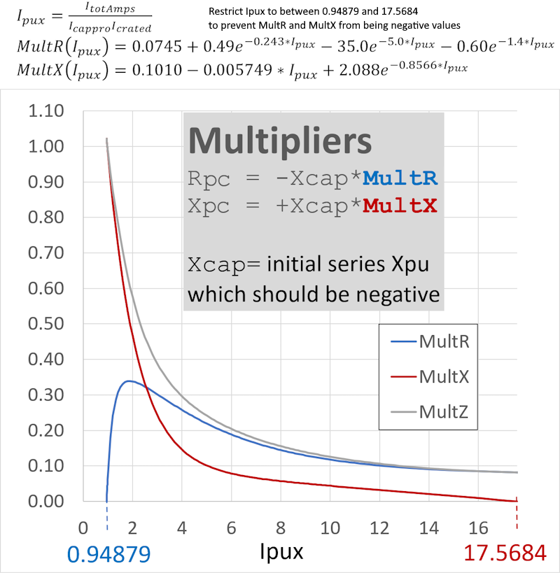
Pseudo-Code for function to Recalculate Rpc, Xpc, and Rmov based on a new value of Itotpu
procedure RecalculateRpcAndXpc(Itotpu) // recalculate Rpc, Xpc, and Rmov using Multiplier functions based on present total current
  Ipux = Itotpu*Ibase/Icrated/Icappro
  If     Ipux < 0.94879 then Ipux = 0.94879   // don't let MultiplierR become negative
  ElseIf Ipux > 17.5684 then Ipux = 17.5684   // don't let MultiplierX become negative
  EndIf
  MultR = 0.0745 + 0.49*exp(-0.243*Ipux) - 35.0*exp(-5.0*Ipux) - 0.60*exp(-1.40*Ipux)
  MultX = 0.1010 - 0.005749*Ipux + 2.088*exp(-0.8566*Ipux)
  if MultR < 0 then MultR = 0 // shouldn't happen but just make sure
  if MultX < 0 then MultX = 0 // shouldn't happen but just make sure
  Rpc = -MultR*Xcap // Xcap = original X
  Xpc = +MultX*Xcap

  Gpc =  Rpc/(sqr(Rpc) + sqr(Xpc))
  Bpc = -Xpc/(sqr(Rpc) + sqr(Xpc))
  Gcap =  Rcap/(sqr(Rcap) + sqr(Xcap))
  Bcap = -Xcap/(sqr(Rcap) + sqr(Xcap))
  Gmov = Gpc – Gcap
  Bmov = Bpc – Bcap;
  Rmov = Gmov/(sqr(Gmov) + sqr(Bmov))
Pseudo-Code for Mode Transitions run at the end of each time-step
  If (Branch Is Bypass) Then // This is Mode 2
    Itotpu = calculate currents from terminal voltage small impedance used for bypass
    Imovpu = 0
    Icappu = 0
    CACHE_BypassSentICAP = false
    CACHE_BypassSentIMOV = false
    If (not CACHE_BypassSentEnergy ) Then // only allow reinsert if not bypass caused by EnergyLim
      if (Itotpu*CACHE_IBase/Icrated <= Iinsert)
         and ( (Imovpu*IBase/Icrated <= Imovlim) or (Imovlim = 0) ) // make sure other bypass conditions are not met
         and ( (Icappu*IBase/Icrated <= Icaplim) or (Icaplim = 0) ) // make sure other bypass conditions are not met
      then
        if not TimeOfBelowIinsertSet then begin
          TimeOfBelowIinsert = PresentTime
          TimeOfBelowIinsertSet = true
        EndIf
        if (PresentTime - TimeOfBelowIinsert >= Tinsert) then begin
          Write Message indicating a transition from BYPASS to NORMAL has been scheduled immediately
          Schedule an event to remove the BYPASS on the next timestep (this event will transition us to Mode 0)
          MOVIsConducting = False
          TimeOfAboveEnerLimSet = False // reset EnerLim timer
        EndIf
      Else
        TimeOfBelowIinsertSet = false // reset Insert timer
      EndIf
    EndIf
  Else
    // The SCMOV model itself will never reinsert after it causes a bypass due to the EnergyMOV > Enerlim.
    // We know that EnergyMOV > Enerlim has happened because CACHE_BypassSentEnergy = TRUE, so the only
    // way we get here is if another stability model or a user event has intentionally removed the Bypass.
    // In that situation we assume the EnergyMOV has dissipated and reset the EnergyMOV and Enerdly timer
    If CACHE_BypassSentEnergy then
      Write message indicating that we are reseting the EnergyMOV and its timer
      CACHE_BypassSentEnergy = FALSE  // reset to allow EnergyMOV to cause it to bypass again
      EnergyMOV = 0                   // clear energy to make 0.0 again
      TimeOfAboveEnerLimSet = False   // reset EnerDly timer
    EndIf

    // Calculate the Currents
    ICapComplex = calculate currents from terminal voltage using original R and X value (per unit system base)
    If MOVIsConducting Then
      ItotComplex = calculate current from terminal voltage and Rpc and Xpc (per unit system base)
      ImovComplex = Complex Difference of (ItotComplex - IcapComplex)
      Itotpu = ItotComplex.Magnitude
      Icappu = IcapComplex.Magnitude
      Imovpu = ImovComplex.Magnitude
      if TimeStep > 0 then EnergyMOV = EnergyMOV + TimeStep*sqr(Imovpu)*Rmov*SystemMVABase
    Else
      Itotpu = ICapComplex.Magnitude
      Icappu = Itotpu
      Imovpu = 0
    EndIf

    // Check the various conditions that will Bypass the device
    If (not CACHE_BypassSentEnergy) AND (Enerlim > 0) AND (EnergyMOV > fEnerlim) Then
      If not TimeOfAboveEnerLimSet Then
        TimeOfAboveEnerLim = PresentTime
        TimeOfAboveEnerLimSet = true
        If Enerdly > 0 Then Write out a messsage indicating that the Enerdlg timer has started
      EndIf
      If (PresentTime - TimeOfAboveEnerLim >= Enerdly) Then
        CACHE_BypassSentEnergy = true
        TimeOfAboveEnerLimSet = False
        Schedule an event to apply a BYPASS on the next Time Step (this event will transition us to Mode 2)
      EndIf
    EndIf

    If (ImovLim <= 0) OR (Imovpu*IBase/Icrated >= Imovlim) Then
      If TimeOfAboveImovLimSet then
	    Write out a messsage indicating that the ImovTup timer has stopped
        TimeOfAboveImovLimSet = False
      EndIf
    ElseIf (not CACHE_BypassSentIMOV) Then
      If not TimeOfAboveImovLimSet Then
        TimeOfAboveImovLim = PresentTime
        TimeOfAboveImovLimSet = true
        If ImovTup > 0 Then Write out a messsage indicating that the ImovTup timer has started
      EndIf
      If (PresentTime - TimeOfAboveImovLim >= ImovTup) Then
        CACHE_BypassSentIMOV = true
        TimeOfAboveImovLimSet = False
        Write message indicating a transition from CAP_MOV to BYPASS has been scheduled to occur in Imovdly
        Schedule an event to apply a BYPASS in Imovdly seconds (this event will transition us to Mode 2)
      EndIf
    EndIf

    If (IcapLim <= 0) OR (Icappu*IBase/Icrated >= Icaplim) Then
      If TimeOfAboveIcapLimSet then
        Write out a messsage indicating that the IcapTup timer has stopped
        TimeOfAboveIcapLimSet = False
      EndIf
    ElseIf (not CACHE_BypassSentICAP) Then
      If not TimeOfAboveIcapLimSet Then
        TimeOfAboveIcapLim = PresentTime
        TimeOfAboveIcapLimSet = true
        If IcapTup > 0 Then Write out a messsage indicating that the IcapTup timer has started
      EndIf
      If (PresentTime - TimeOfAboveIcapLim >=; IcapTup) Then
        CACHE_BypassSentICAP = true
        TimeOfAboveIcapLimSet = False
        Write message indicating a transition from CAP_MOV to BYPASS has been scheduled to occur in Icapdly
        Schedule an event to apply a BYPASS in Icapdly seconds (this event will transition us to Mode 2)
      EndIf
    EndIf

    // Manage the Mode transitions between Mode 0 and 1
    If MOVIsConducting Then
      if (Itotpu*CACHE_IBase/Icrated/Icappro <= Ithresh) Then
        MOVIsConducting = False
        Write message indicating a transition from CAP+MOV to NORMAL
      Else
        RecalculateRpcAndXpc(Itotpu) // recalculate Rpc and Xpc (see other procedure above)
      EndIf
    Else
      If (Itotpu*IBase/Icrated/Icappro >   fIthresh) Then
        MOVIsConducting = True // transition to MOV mode
        RecalculateRpcAndXpc(Itotpu) // recalculate Rpc and Xpc (see other procedure above)
        Write message that we have transitioned from NORMAL to CAP+MOV Mode
      EndIf
    EndIf
  EndIf