Generator models are the most complex models in a transient stability tool. Generators can have many classes of dynamic model assigned to them including the following types.
- Machine Model (or converter model for renewal
- Exciter Model (or electrical control for renewable)
- Governor Model (or mechanical control for renewable)
- Stabilizer Model (or pitch control)
- Under Excitation Limiter
- Over Excitation Limiter
- Compensator Model
- Aerodynamic Model
- Pref Controller
- Plant Controller
- AGC Controller
- Relay Models
You may define multiple models of each class of model to a generator, but for all types of models (except relays) there can be only one active model with a Criteria that evaluates to TRUE.
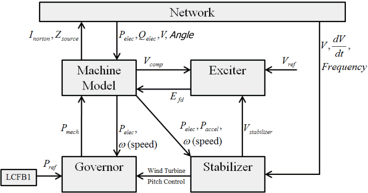
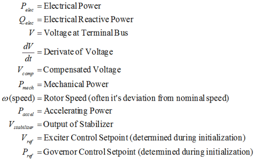
The relationship between the four primary model (machine, exciter, governor, and stabilizer) is shown in the figure below, along with the variables which are passed between the models. This is not an exhaustive list, but represents the typical relationships between the models. For renewable energy generator models (wind, solar, energy storage, solar pv, etc.), similar relationships exist between a wind machine model, electrical model, mechanical model, and a pseudo-governor model. For more information about wind turbine modeling in Simulator, see the Renewable Energy Generation Modeling help topic.


Governor Response Limits
There is a special generator field in Simulator called Transient Stability\Governor Response Limits. The field determines the response of the governor control limits during a transient stability run. Options are Normal, Down Only, or Fixed. When loading from an EPC file a Baseload flag value of 0 maps Normal, 1 maps to Down Only, and 2 or more maps to Fixed.
A value of Normal means that the limits specified in the governor model will be used for the simulation. A value of Down Only means that the upper limit is set equal to the initial condition value (and thus control can only go down). A value of Fixed means that both the upper and lower limits are set equal to the initial condition (and thus control will be approximately constant). Note that the power output of the generator can still vary for those turbines whose MW output is sensitive to speed (because the speed can obviously still vary).
Also, this field will always be shown as a default field when looking at a case information display showing a list of governors.
Special Accommodation for handling Line Drop Compensation
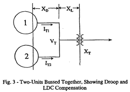
In modeling the WECC system, a stability issue was encountered at several hydro units such as John Day. The issue, which is described in the papers listed below, arises because of how the exciters for some hydro units with dual generators have been configured to enhance system voltage stability. Rather than regulating their terminal voltage, or a point internal to the generator (using compensation), the generator exciters have been configured using line drop compensation to regulate a point midway through the step-up transformer. This is illustrated in the below figure, which reproduces Figure 3 from the Murdoch/Sanchez-Gasca paper below. The advantage of this approach is it allows the generator exciters to directly regulate a point close to the transmission system (perhaps 50 to 80% of the way through the step-up transformer). If there is just one generator feeding through the transformer then this control can be modeled in the normal fashion. However when there are two generators, an extremely common configuration at hydro plants, physically the exciter inputs at each plant need to receive the currents from both machines in order to insure they are both regulating the same line drop compensated voltage. If this is not done, then the controls will end up fighting each other, driving the excitation current for one generator to its maximum and for the other generator to its minimum. Therefore to correctly model this situation, the PowerWorld Simulator transient stability excitation modeling code has been enhanced to include both generator currents in situations in which line drop compensation causes the regulated voltage to be beyond the generator’s terminal. Otherwise the traditional code is used.

NOTE:
When modeling a GENCLS model with H=0 and D=0 it is treated as an infinite bus.
A. Murdoch, J.J. Sanchez-Gasca, “Excitation Control for High Side Voltage Regulation,” Proc. IEEE PES 2000 Summer Meeting, July 2000, pp. 285-289.
C.W. Taylor, “Line drop compensation, high side voltage control, secondary voltage control – why not control a generator like a static var compensator,” Proc. IEEE PES 2000 Summer Meeting, July 2000, pp. 307-310