The Transient Limit Monitors page is found on the Transient Stability Analysis dialog.
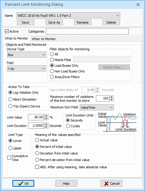
When inserting a new transient limit monitor you are presented with the following dialog. This gives you great flexibility in defining monitors for the various values which can be recorded in a transient stability run. Note that there are some very simple Generic Limit Monitors for synchronous machines which are define as part of the Transient Stability options that may also be of use.

In the top portion of the dialog you first give the transient limit monitor a name. There is then an option to make a transient limit monitor Active or not. Below the middle of the dialog there is the Action To Take options: Log Violation Only, Abort Simulation or Trip (Open) Device. The Log Violation Only will show the violation only in the message log. The Abort Simulation will abort simulation at a specified time after a violation of the monitor occurs. The Trip (Open) Device will option to trip/open a device" if a monitoring violation occurs (this works for Buses, AC Lines, Generators, Loads, and DC Lines). There is also a choice for Maximum number of violations of this limit monitor to store. This is needed so that too many limit violations of the same limit monitor are not created. If you know the lowest 100 bus frequencies, you don't need any more than that.
The option Maximum Sort Field was Added in Version 23 to a user to specify which violations to keep. Prior to Simulator Version 23, the first 100 violations in time-order would be kept and after the Maximum number of violations of this limit monitor was reached no additional TSLimitViolations would be stored. The Maximum Sort Field gives 5 options to specify which violations should be kept. The options are the following 5 fields stored with the TSLimitViolation: ValueTime, ValueStartTime, ValueExtremeTime, ValueExtreme, or ValueExtremeConv. When deciding which TSLimitViolation objects to create once the MaxViolStore count is reached, this sort field determines which violations to keep. The default choice is ValueTime which is the time at which all conditions for a violation to be recorded was met and thus our old default of the first violations in time-order. We expect that the ValueExtreme and ValueExtremeConv will also b used extensively as these choices will record as a violation the signals that have the extreme deviation from the Limit Value during the simulation.
The Categories input is a comma-separated list of user specified category names. Categories determine which Transient Limit Monitors are applied to each contingency. See the Contingency Category topic for more information.
There are then choices to specify the device type and a filter which together will determine all the objects which are ultimately monitored by the transient limit monitor. Note that a decision regarding which objects meet the filter will be done at the start of a stability simulation based on the steady state values of the power system. You then specify which field of the device type will be monitored.
The top portion of the dialog describes which particular object/field pair traces are going to be monitored. The bottom portion of the dialog will define what shape of the trace will be considered a limit violation. For the basic limit monitor you specify three values: Limit Value, Limit Duration, and Limit Type. These choices work together to determine what is considered a violation. Typically limit types are Lower and a trace will be considered violated if the value is below the Limit Value for a duration specified by Limit Duration. For a Upper limit type, then it must be above the Limit Value instead. The choice for Meaning of the values specified affect how the Limit Value and values specified for special triggers discussed shortly are interpreted. The first choice is Actual Value which simply means the limit value represents the exact numerical value considered a violation. The other choices are based on a deviation from the initial steady state value or a percent or percent deviation from the initial value. As an example, for a system with a 60 Hz nominal frequency, the following are equivalent: [Actual value = 59.6 Hz] and [Deviation from initial value = -0.4 Hz]. Similarly, when monitoring a voltage the following are equivalent: [Percent of initial value = 70%] and [Percent deviation from initial value = -30%]. Finally there is a option ABS: After using meaning, take absolute value, which will take the absolute value of the value.
The check-box option for Cumulative Time was added in Version 22, build on September 28, 2022. Normally when Cumulative Time is not checked, if a signal drops below the Limit Value threshold briefly but does not stay below for the full Limit Duration, then immediately upon moving back on the good side of the Limit Value the timer is reset and the signal will need to be violated the Limit Valuefor an additional full Limit Duration. When choosing Cumulative Time, then the timer is not reset and a signal is considered violated if the cumulative time during the simulation for which the signal is violated exceeds the Limit Duration. As an example, if Limit Duration = 0.15 seconds, when using Cumulative Time, if a signal drops below a low limit for 0.1 seconds, swings back above for a while and then drops below again for an additional 0.05 seconds, it would be considered to have violation the 0.15 Cumulative LImit Duration.
When to Monitor
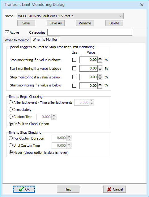
By default the transient limit monitoring does not start until after the last user-specified contingency event occurs. This is done because values such as voltage will obviously be violating during a bus fault (they'll be zero!), so what you really want to know is whether the voltage is below a value for a specified duration after the fault clears. To change this default behavior, there are also special options available by clicking on When to Monitor tab of this dialog. These are shown in the dialog below. The values specified here will obey the choice for Meaning of the values specified discussed above.
The settings regarding the Time to Begin Checking are the same options as present for the Global Transient Result Options. Setting these to default will just use those global settings, or you can override these settings for a specific Transient Limit Monitor. You may also configured when to stop checking a particular Limit Monitor.

Built-In Transient Limit Monitors for WECC Standards
WECC criteria changed in 2016 and 5 built-in Transient Limit Monitor definitions were created to describe these signal requirements. These can be inserted going to the Transient Limit Monitors case information display choosing the Records menu dropdown from the case information toolbar and then choosing the appropriate option for Build WECC 2016 Fault Clearing Standard Monitors or Build WECC 2016 No Fault Standard Monitors. Note that by default all these 2016 standard monitors are always inserted into a new power system case. The standards are initially marked as Active = NO however so they must be set to Active = YES in order to use them.
The WECC 2016 Fault Clearing Standard Monitors create the following transient limit monitors.
-
WECC 2016 Fault WR1 1.3
-
WECC 2016 Fault WR1 1.4 Part 1
-
WECC 2016 Fault WR1 1.4 Part 2
The WECC 2016 No Fault Standard Monitors create the following transient limit monitors.
-
WECC 2016 No Fault WR1 1.5 Part 1
-
WECC 2016 No Fault WR1 1.5 Part 2
For Studies done before 2016, Simulator has built in the ability to automatically insert transient limit monitors which represent WECC Category B and WECC Category C standards. This can be inserted going to the Transient Limit Monitors case information display choosing the Records menu dropdown from the case information toolbar and then choosing the appropriate option for Build WECC Pre-2016 Category B Standard Monitors or Build WECC Pre-2016 Category C Standard Monitors.
The WECC Category B Standards create four transient limit monitors.
- WECC Category B Voltage Dip for Non-Load Buses will monitor all non-load buses for any voltage dip of 30% below the initial voltage value at any time.
- WECC Category B Voltage Dip for Load Bus will monitor all load buses for a voltage dip of 25% below the initial voltage at any time.
- WECC Category B Voltage Dip for Load Bus Duration will monitor all load buses for a voltage dip of 20% below the initial voltage for a duration of 0.3333 seconds (20 cycles) and the dialog is shown above.
- WECC Category B Frequency will monitor all load buses for a frequency dip below 59.6 Hz for a duration of 0.10 seconds (6 cycles) and the dialog is shown to the right as an example.
The WECC Category C Standards create three transient limit monitors.
- WECC Category C Voltage Dip Any Bus will monitor all buses for a voltage dip of 30% below the initial voltage at any time.
- WECC Category C Voltage Dip Any Bus Duration will monitor all buses for a voltage dip of 20% below the initial voltage for a duration of 0.6667 seconds (40 cycles).
- WECC Category C Frequency will monitor all load buses for a frequency dip below 59.0 Hz for a duration of 0.10 seconds (6 cycles).