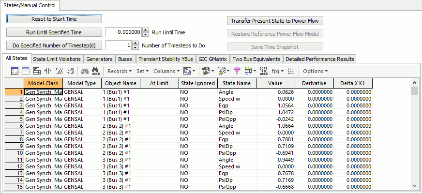
The States/Manual Control page is found on the Transient Stability Analysis dialog. This page provides a means to manually control a transient stability run and view generator and bus states at each step of the process. It will be very helpful in determine which part of the system is causing an instability. It is also helpful to look at initial State Limit Violations as described below. Also note that when you first open the Transient Stability Dialog, Simulator does not immediately initialize the transient stability simulation. This initialization obviously occurs when you start simulation, but it also occurs when you switch to either the States/Manual Control or the SMIB Eigenvalues.
One particular good use of this section is to sort by the Derivative column under the All States sub-tab to ensure of that the state derivatives are all near zero at the initialized system state. Note: many induction motor states will never be exactly zero because their initial states must be determined by an iterative process, but in general derivatives should be very near zero. Another good use of this section is to look at the initial condition State Limit Violations.

Reset to Start Time
Click this button to reset the simulation back to the start time as specified on the Simulation Control page.
Run Until Specified Time
Click this button to run to the specified Run Until Time. The Run Until Time should be set in seconds. The simulation is run from the present time to this specified time. The current time is shown in the Simulation Status field that is displayed at the top of the Transient Stability Analysis dialog. The Run Until Time must be later than the present simulation time.
Do Specified Number of Timestep(s)
Click this button to run the specified Number of Timesteps to Do. The simulation starts at the present time and does the number of timesteps. The current time is shown in the Simulation Status field that is displayed at the top of the Transient Stability Analysis dialog.
Transfer Present State to Power Flow
Click this button to transfer the present state resulting from the transient stability analysis to the power flow model. The present state is not transferred to the power flow model when running the transient stability analysis when not using the manual mode.
Restore Power Flow Model
Click this button to restore the power flow model to the pre-transient stability analysis state. This option can be used when the transient stability state information has been transferred to the power flow model.
Save Time Snapshot
Click this button to save the power flow model to file with the present transient stability results. Transient stability results will only be saved if choosing a file type of either *.pwb or *.aux. If the transient stability state has been transferred to the power flow model, the power flow model is first restored to the pre-transient stability analysis state before saving.
All States
This sub-tab contains a list of every state in the dynamic simulation. The Value of each state is listed along with the Derivative of the state.
State Limit Violations
This sub-tab contains a list of all the state limit violations in the initialized system. This State Limit Violations are also organized into lists of All, Modified, and Not Modified. The list of Modified State Limit Violations shows at the initial condition a list of violations for which the limits have been temporarily changes according to the Option for Handling of Initial Limit Violations.
Generators and Buses
This sub-tab contains a list of all the present terminal values for the generators and buses. These are the same values you can see on the Transient Stability Data: Object Dialogs and include fields such as Field Voltage, Rotor Angle, Accelerating MW, etc...
In the Generators sub-tab, in addition to getting all the present terminal values for the generators by right-clicking on the Generator entries and choosing Save Two Bus Equivalent from the local menu, you can save the Two Bus system from the selected bus to an infinite bus. When writing out this two bus equivalent model, generators automatically set to AVR = NO In addition when saving the Two Bus equivalent it can save a GENCLS model on the slack bus saved to represent an infinite bus.
Transient Stability YBus
This sub-tab displays the transient stability Y-Bus following the last transient stability analysis timestep.
GIC GMatrix
The GMatrix page shows the entries in the G (conductance) matrix. The entries are for the parallel combination of all three phases.
Two Bus Equivalents
This let you save the Two Bus system from the selected buses to an infinite bus. When writing out this two bus equivalent model, generators automatically set to AVR = NO. In addition when saving the Two Bus equivalent it can save a GENCLS model on the slack bus saved to represent an infinite bus. You can select the file format (PowerWorld, PSSE or PSLF) to save the equivalent. Also a Directory Location can be specified to save the equivalents and also a Playback File Name can be specified. The equivalent can include the cross compound generators at a bus by checking the specified check box. The button Save All Selected Two Bus Equivalents in Desired Formats will automatically save the buses set to Yes in the Save Two Bus Equivalent column in the table.