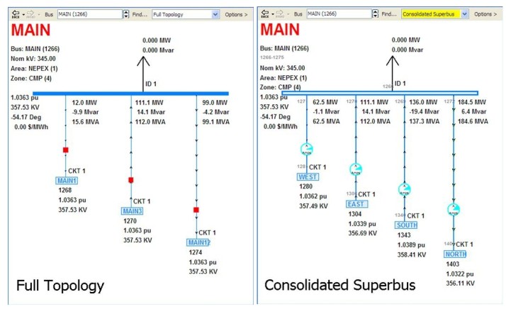
Simulator’s Bus View provides a feature that allows a Full-Topology Model to be navigated using the Consolidated Representation, in which only the primary buses are shown. This gives the appearance to the user of navigating the electrically equivalent planning case.
The Consolidated Superbus View is accessed from the Bus View Display. If the current case is set up such that superbuses can be identified, there will be a drop-down box at the top of the Bus View Display that will allow switching between the Full Topology representation and the Consolidated Superbus representation.
The Consolidated Superbus View has the following conventions:
- Shows radial-connected generator, load, and switched shunt buses above the main (primary) bus
- For series connections of buses, the main branch shown will be the first branch that is marked as NOT available for consolidation (i.e. AllowConsolidation = NO)
- All generator, load, and switched shunt devices will appear connected to their Primary Bus instead of the actual bus
- Only branches that connect different superbuses will be shown. This means that closed circuit breaker will not appear on the consolidated superbus view because they connect two buses that are in the same superbus.
When saving a Consolidated Case or when viewing the Consolidated Superbus in the Bus View, generally open switching devices are maintained in the model to show where they are. If a CLOSED switching device is parallel with a open switching device it will not display the open switching device. CLOSED switching devices in this situation are unusual as they must be specified as Consolidate=NO or part of an interface or tie-line, so this is a special situation.
An example full-topology model is shown below. Each gray region represents a superbus. The large buses and numbers in each superbus represent the primary bus for that superbus.
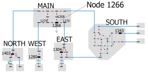
The associated full-topology bus view and the consolidated superbus view for the above model is shown below: