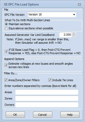
The GE EPC File Load Options dialog will open when choosing to open or save a GE EPC case "with options".

EPC File Version
Set this to determine what version of the EPC file is being read or saved.
What To Do With Multi-Section Lines
This option is only relevant when loading in data. This option allows multi-section lines to be maintained as they are defined in the file or have their sections merged into a single equivalent line.
Assumed Generator Var Limit Deadband
This option is only relevant when loading in data. This options specifies a deadband used to determine if generators should be on or off AVR control. If the difference between the Max and Min Mvar output of a generator is less than this deadband, Simulator will set the AVR flag for a generator to NO.
GE Base Load Flag Setting
When opening a file, the GE Base Load Flag setting will be used to set the Post-CTG Prevent AGC Response field in Simulator. The caption will be the following: if GE Base Load Flag > 0, then Post-CTG Prevent Response = YES, else Post-CTG Prevent Response = NO. Note: This is the default setting.
When loading an EPC file, the GE Base Load Flag is used to set the Governor Response Limits field with a generator. This field is used to determine governor response settings during a transient stability run. This field is set directly to the GE Base Load Flag regardless of the input option setting. The possible settings are 0 = Normal, 1 = Down Only, and 2 = Fixed.
When saving a file, the caption will be the following: if Post-CTG Prevent Response = YES, then set GE Base Load Flag = 2, else set GE Base Load Flag = 0 (Only done if Governor Response Limits = Normal). The Post-CTG Prevent AGC Response field in Simulator will be used to set the Base Load Flag setting in the EPC file only if the Governor Response Limits field is set to Normal for a generator. Otherwise, the GE Base Load Flag will be set to the number corresponding to the Governor Response Limits field: Down Only = 1 or Fixed = 2.
Estimate voltages at new buses and smooth angles across new lines
This option is only available when appending data to an existing case. By default, Simulator assumes that the voltages and angles in the new data are not known and must be estimated based on existing voltages already in the case. This assumption could be wrong if appending large sections of a case, i.e. such as a new island, or providing voltages that are already good estimates in the appended data. There is no way to determine for sure if the voltages provided in the appended data are "good" or not, thus the user can decide this.
Filter By
If desired, only data in with specific areas, zones or owners can be loaded from the EPC file by using this option. Checking the Area/Zone/Owner Filters box will display the edit boxes for entering the Area, Zone, and Owner numbers. You can also check the Include Tie Lines box to read in branches for which only one of the two terminal buses is designated with the specified area, zone or owner. Leaving this box unchecked will force the requirement that BOTH branch terminal buses meet the specified areas, zones or owners for it to be read from the EPC file.
See the Case Formats topic for information on special handling of data that occurs when loading a case using the GE EPC file format.