Available Generation Control (AGC) Modeling
Added in Version 19
Available Generation Control can be modeled in transient stability by defining an Area AGC model along with Generator AGC Controllers. The signals for this structure are shown in the following image.
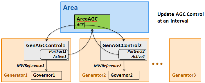
AreaAGC Model assigned to an Area object
Initially there in only one Area AGC Model which has the following 8 fields.
|
Parameter |
Description |
Units |
|
Bus |
Specification of the bus at which frequency measurement is taken |
|
|
Bias |
Frequency Bias [MW/0.1Hz] |
MW/0.1Hz |
|
Deadband |
No response if ACE within thisdeadband |
MW |
|
PanicHighOn |
PanicMode is entered if the frequency goes above this |
Hz |
|
PanicHighOff |
If a panic mode is entered due to HIGH frequency, this is the frequency in Hz BELOW which the system must fall to exit the panic mode |
Hz |
|
PanicLowOn |
Panic mode is entered if the frequency goes below this |
Hz |
|
PanicLowOff |
If a panic mode is entered due to LOW frequency, this is the frequency in Hz ABOVE which the system must recover to exit the panic mode |
Hz |
|
UpdateTime |
AGC UpdateCycle Time in Seconds. AGC signals are updated at this interval |
Seconds |
Notes about the Area AGC Model
- Area Frequency is measured at the bus indicated by the AreaAGC Model.
- The ACE calculation uses the Bias and Deadband terms as well as the list of Area to Area Tie-Lines that exist in the power system model.
- Panic Mode is a special feature that will cause the response of the various Generator AGC Controllers to change. When in Panic mode then generators with an AGC control model which has a mode of either LOCAL (2) or BASELOAD (3) will participate in AGC just like they were set to a mode of ON (1). Also, when in panic mode, the ACE calculation will no longer include the tie-line flow portion of the calculation meaning that the ACE is only concerned with returning the system to nominal frequency when in panic mode.
AGC update is done at user-specified interval of UpdateTime seconds (specificified in the AreaAGC). Within the numerical integration this is handled at the start of each on each time-step and thus appears algebraic to the differential equations. When the update is done it performs the following steps
- CalculateACE
- Call UpdateAGCSignal on each generator in the area
- Call RespondToAGCSignal on each generator in the area
This also requires an update of many other models which receive a MWReference input signal (such as Pref on most governor models), but this will be discussed below.
AGC ACE Calculation
The area designation in the power system model determine the list of area to area tie-lines. ACE attempts to bring tie-line flows back to the initial condition. The ACE Calculation is as follows
- Normal: ACE = (MeasBusFreq - NominalFreq)*10*Bias + (SumTieFlows - InitialTieFlow)
- Panic Mode: ACE = (MeasBusFreq - NominalFreq)*10*Bias
For both there is also a Deadband applied so that if the absoluate value of ACE is less than the deadband, then the ACE = 0.0.
Determination of which Generators to respond and Participation Factor Summation
Use the ACE value for the entire area, each generator in the area is then processed to determine whether the generator will respond and the summation of the participation factors. Below is some pseudo-code describing this response with each generator flagged as AGCActive as well as the summation PartFactSum maintained.
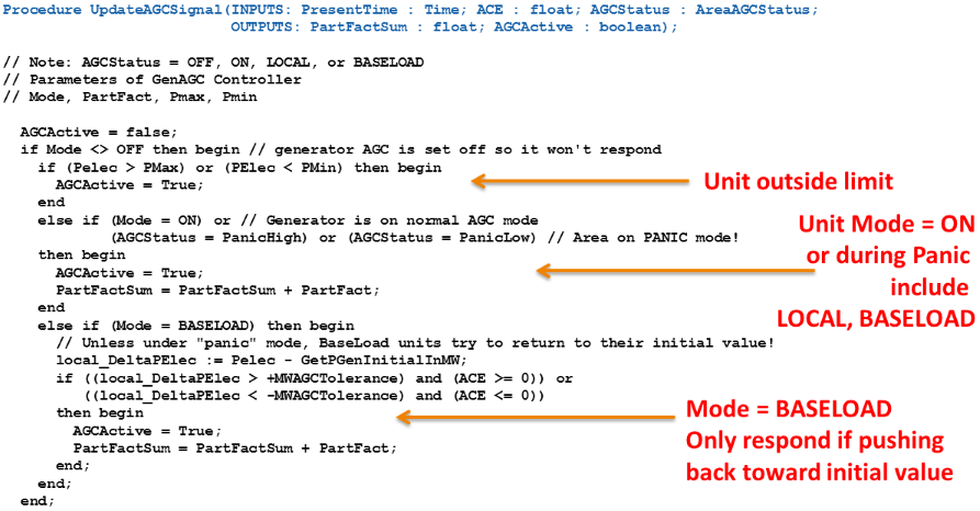
Then using this list of generators and summation, each generator responds to the ACE signal and the participation factor summation based on its AGC Controller which will be described next.
Generator AGC Controller Model
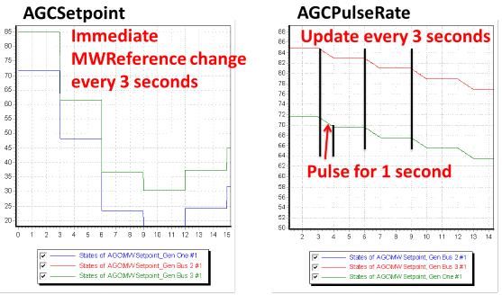
There are 2 primary types of AGC controllers: AGCSetpoint and AGCPulseRate. The AGCSetpoint controller will take the signals received from the AreaAGC model and interpret them as an immediate change in the MWSetpoint of the generator. The AGCPulseRate controller will take the signals received and instead either ramp up or ramp down its MWSetpoint at a predefined rate.
AGC Controller Mode
One thing which is common to the AGC Controller models however is the concept of a Mode for the controller. Each controller has an integer parameter called mode which can have 4 values which are interpreted as follows
- 0 (OFF) : means the generator is ignored for AGC purposes (its MWSetpoint remains constant)
- 1 (ON) : means the generator participates in AGC
- 2 (LOCAL) : means the generator normally does not participate in AGC, but during Panic Mode it will participate
- 3 (BASELOAD) : means it only participates if moving its reference pushes the generator back toward its initial value
AGCSetpoint
The AGCSetpoint model has the follow 5 fields.
|
Parameter |
Description |
Units |
|
|
Mode |
Integer Value 0 (OFF), 1 (ON), 2 (LOCAL), or 3 (BASELOAD). See description above for details. |
||
|
Default |
Integer Value 0 (No, use specific values), 1 (get values from case) If value set to 1, then PartFact, Pmax, and Pmin will be obtained from the power flow input data and stability record values are ignored |
|
|
|
PartFact |
Participation Factor for us in AGC |
|
|
|
Pmax |
Maximum Power reference signal output |
MW |
|
|
Pmin |
Minimum Power reference signal output |
MW |
AGCPulseRate
The AGCPulseRate model has the follow 8 fields.
|
Parameter |
Description |
Units |
|
|
Mode |
Integer Value 0 (OFF), 1 (ON), 2 (LOCAL), or 3 (BASELOAD). See description above for details. |
||
|
Default |
Integer Value 0 (No, use specific values), 1 (get values from case) If value set to 1, then PartFact, Pmax, and Pmin will be obtained from the power flow input data and stability record values are ignored |
|
|
|
PartFact |
Participation Factor for us in AGC |
|
|
|
Pmax |
Maximum Power reference signal output |
MW |
|
|
Pmin |
Minimum Power reference signal output |
MW |
|
|
PulseRate |
Rate at which the MWReference signal changes |
MW/Second |
|
|
PulseLength |
Length of time that the pulse up or down occurs. This should normally be less than the Area AGC Model’s UpdateTime. Thus the UpdateTime may be 10 seconds and PulseLength is 2 seconds |
Second |
|
|
PulseLengthPanic |
When Area AGC Model enters panic mode, then you can increase the length of the pulse. |
Second |
Response of Generator to AGC Signal
Each generator then responds based on PartFactSum calculated. The following is pseudo code for the AGCSetpoint and AGCPulseRate models
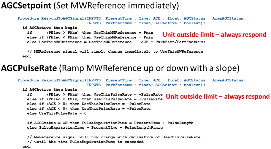
The following images demonstrate how the MWSetpoint of the geenerators respond for the two types of AGC Controllers.
Passing the new MWReference Signal
The new MWReference will then be passed to the appropriate generator model to respond. This will depend on which generator models are defined with the following precedence.
- A Plant Controller is defined and active (REPC_A, REPC_B)
- A Pref Controller is defined and active (LCFB1, WTGTRQ_A)
- WT3P (special stabilizer model for first generation wind turbine models)
- A Governor model is defined and active (most of the dozens of governor types have a "Pref")
- Mechanical power for the active machine model will be changed appropriately
- If there isn't even a machine model, then the algebraic Electrical Power of the generator will be changed.
Taking a a MWReference signal an modifying a particular transient stability model is unique for each model. This is done by Simulator using algebra with the following assumptions.
- Assume the generator is operating at steady state (nominal frequency)
- Calculate Pref that would be needed when initializing the model from steady state if the MW output was equal to the new MWReference.
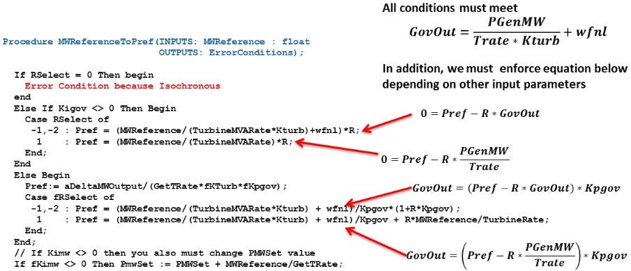
This makes the assumption that the AGC system is always trying to drive the system back to nominal frequency. It is important to realize that for some models it is not possible to do this calculation. For example, isochronous governor models (Rselect=0 or R=0 on GGOV1 governor for example. Let's use GGOV1 as an example.
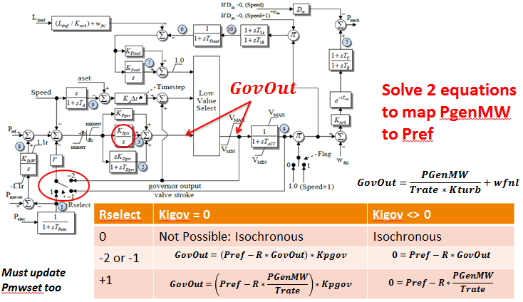
Using these dependencies, the new value of Pmset and Pref for the GGOV1 model are updated as shown in the following pseudo-code.
