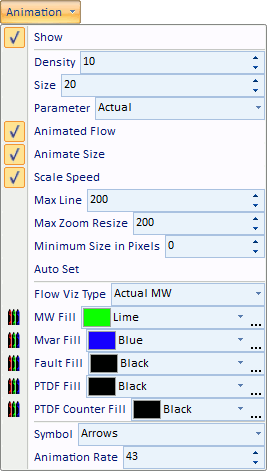
The fields on the Animated Flows page of the Oneline Display Options dialog are used to customize the appearance of the animated flows on the oneline diagram.
Show Flow Symbols
Determines whether power flows are animated on the onelines. If this option is not checked, then no flow symbols appear on the oneline.
Show Flows On
Allows you to choose whether or not to display animated flows individually on Branch, Load, Generator and Shunt objects. Uncheck the box(es) for the objects that you do not wish to display animated flows.
Base Flow Scaling on
Animated flows on onelines may depict either actual power flows or power transfer distribution factors, depending on what you choose here. You can also choose to animate both the MW and MVAR flows or the MW and PTDF flows simultaneously. The Custom Float 1 option allows user specification of a value to depict in the flow animation. To use this option, values should be entered in the Custom Floating Point 1 field for the appropriate devices.
Animate
This option determines whether or not the flow arrows are mobile or stationary on the oneline diagram. Unchecking this box will cause the flow arrows to remain stationary on the diagram.
Scale Speed of Flow
Checking this box will cause the arrows to flow at a speed proportional to the represented quantity. When it is not checked, all of the flows will be at the same speed.
Scale Size of Flow
If checked, the size of the animation symbols will vary to represent the magnitude of flow on the element (respective of the Animation Parameter.) Otherwise, the symbol size will be the same on all devices regardless of the magnitude represented.
Reset Animated Flow Offsets
This button allows the user to reset the animated flows to start at a specified offset position. Mostly this would be used to reset the offset to 0, which would cause the animated flows to start at the beginning of the line or element. Since the animation moves the flow arrows every time the load flow is resolved, resetting flows to a specific offset could be useful for comparing different load flow solutions by looking at differences in the animated flow objects.
Set Size, Density, and Reference Values for this oneline
Simulator detects the current zoom level and object parameters of the selected oneline diagram, and automatically adjusts the animation settings in an attempt to optimize the animation quality.
Size
Determines the relative size of the animated flows on the devices. Increasing this number increases the size of the flow symbols. This field may range from 1 to 999.
Density
Determines the relative density of the animated flows on the devices. Increasing this value causes Simulator to display a greater number of flow symbols per unit distance on the oneline. This value may range from 1 to 999.
Scaling Based on
Determines whether the size and speed of animated flows represent actual flow or percentage loading. This option applies only to transmission lines and transformers as flows on other devices, such as loads and generators, always represent actual flow.
Max. Zoom Level to Scale Size
As a oneline is zoomed, the animated flow symbols increase in size. The value of Max. Zoom Level to Scale Size caps the size of the animated flows so that zooming beyond this level results in no further increase to the size of the flow symbols.
Maintain Density above Maximum Zoom Level
As a oneline is zoomed, the animated flow symbols decrease in density. Checking this box maintains the density of the animated flows after the maximum zoom level has been reached.
Minimum Size in Pixels for In-service Elements
Allows the specification of a minimum size for the animated flow objects for power systems elements that are in-service. The flow objects are sized based on the flow through the element. For elements with very small flows, it is often difficult to see the flow objects, and the minimum size can be set to make these flow objects more visible. The larger the minimum size value becomes, the more uniform the flow objects will become as elements are no longer sized based on their actual flow but rather the minimum size.
Reference Values for Scaling
Maximum flow reference for sizing the animated flows. The lower the MVA reference, the larger the animated flows appear on the oneline diagram as the actual flow value is compared to the reference value for scaling.
Symbol Shape
Simulator can display animated flows using directional arrows, circles, squares, or triangles.
Animation Rate
If the oneline animation is too fast or too slow, the animation rate can be adjusted by moving the slide bar.
Shows the fill color used for the animated flows if Use Fill Color is checked. Double-click on these fields to change the colors of the six different types of animated flows.
Use Fill Color
Checked if animated flow symbols should be filled using the Fill Color.
Show PTDF Counter Flow
Check this option if you wish for PTDF values that are in the opposite direction of the actual flow to be displayed using a different symbol color when visualizing PTDFs.
Many of these same options are available on the Animation Menu found on the Options ribbon tab.
